Path prediction system, path prediction method, and program
A prediction system and prediction method technology, applied in directions such as road network navigators, can solve problems such as inability to make predictions
- Summary
- Abstract
- Description
- Claims
- Application Information
AI Technical Summary
Problems solved by technology
Method used
Image

Examples
no. 1 Embodiment approach )
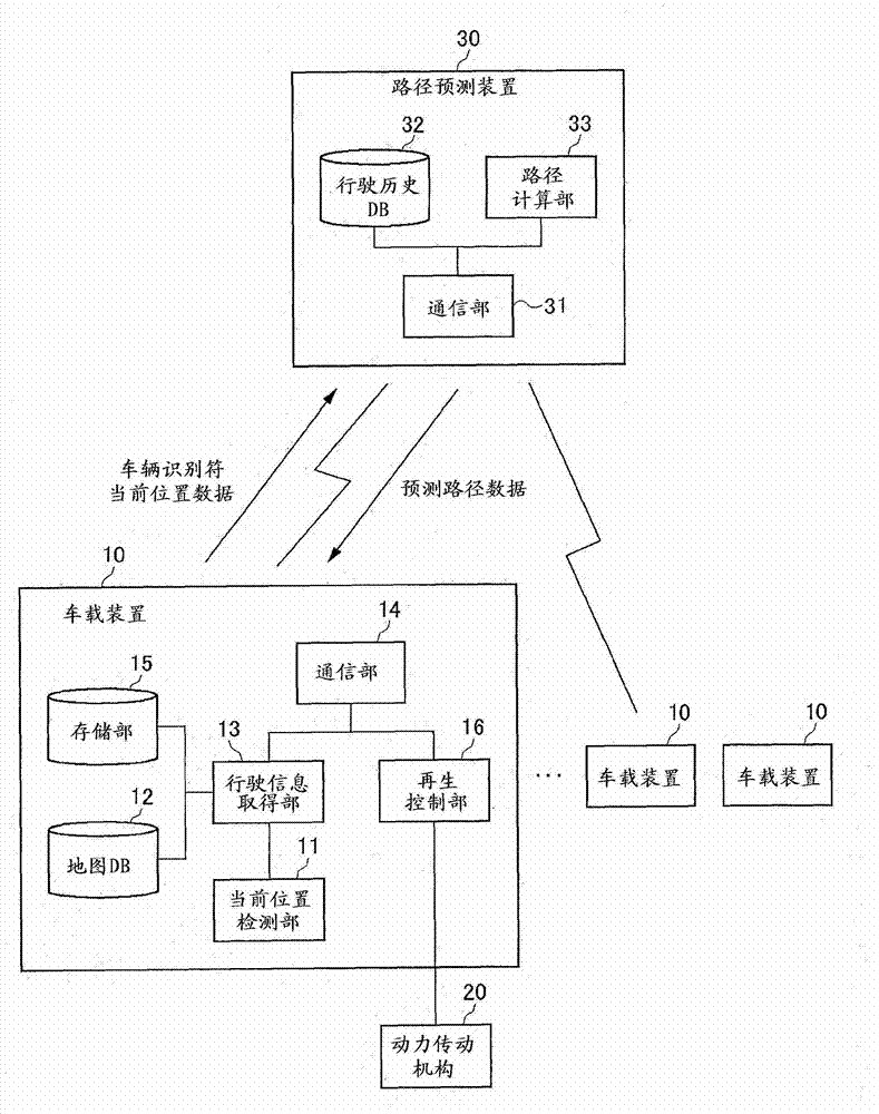
[0027] figure 1 It is a figure which shows the structure of the route prediction system of 1st Embodiment. In this embodiment, an example is given in which the result of the route prediction performed by the route prediction system is used in regeneration control.
[0028] The route prediction system includes an in-vehicle device 10 mounted on a vehicle, and a route prediction device 30 that collects travel history data from the in-vehicle device 10 and performs route prediction based on the travel history data. The vehicle-mounted device 10 is installed in a plurality of vehicles, respectively. The in-vehicle device 10 and the route prediction device 30 are wirelessly connected via a network. The route prediction device 30 collects travel history data of a plurality of vehicles. In addition, when there is a route prediction request from the vehicle-mounted device 10 , the route prediction device 30 calculates the predicted route through the route calculation unit 33 , and ...
no. 2 Embodiment approach )
[0047] Next, a route prediction system according to the second embodiment will be described. The basic configuration of the route prediction system of the second embodiment is the same as that of the route prediction system of the first embodiment. In the route prediction system of the second embodiment, the route calculation method performed by the route calculation unit 33 is different from that of the first embodiment.
[0048] Figure 7 is a flowchart showing the operation of the route prediction device 30 . When the route calculation unit 33 of the route prediction device 30 receives the vehicle identifier and current position data transmitted from the vehicle-mounted device 10 ( S30 ), it reads the travel history data of all vehicles from the travel history DB 32 ( S32 ).
[0049] Next, the route calculation unit 33 calculates the predicted route of the target vehicle based on the travel history data of all the vehicles ( S34 ). Specifically, the weight coefficient α ...
no. 3 Embodiment approach )
[0052] Next, a route prediction system according to a third embodiment will be described. The basic configuration of the route prediction system of the third embodiment is the same as that of the route prediction system of the first embodiment. The route prediction system of the third embodiment differs from the first embodiment in that vehicle type data is stored in the travel history DB 32 of the route prediction device 30 .
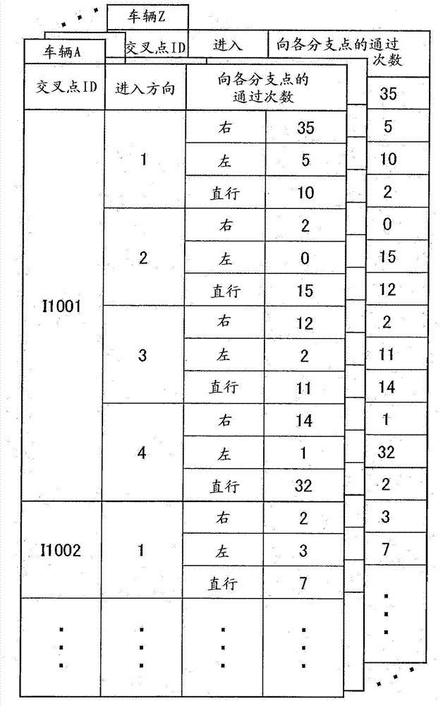
[0053] Figure 8 It is a diagram showing an example of data stored in the travel history DB 32 of the route prediction device 30 . Such as Figure 8 As shown, in addition to the driving history data of each vehicle, data of the type of each vehicle is also stored.
[0054] Figure 9 is a flowchart showing the operation of the route prediction device 30 . When the route calculation unit 33 of the route prediction device 30 receives the vehicle identifier and the current position data transmitted from the vehicle-mounted device 10 (S10), it reads th...
PUM
 Abstract
Description
Claims
Application Information
 - R&D
- Intellectual Property
- Life Sciences
- Materials
- Tech Scout
- Unparalleled Data Quality
- Higher Quality Content
- 60% Fewer Hallucinations
Browse by: Latest US Patents, China's latest patents, Technical Efficacy Thesaurus, Application Domain, Technology Topic, Popular Technical Reports.
© 2025 PatSnap. All rights reserved.Legal|Privacy policy|Modern Slavery Act Transparency Statement|Sitemap|About US| Contact US: help@patsnap.com