Uplink signal sending method and device

A signal transmission and signal technology, applied in the field of uplink signal transmission methods and devices, can solve the problems of affecting uplink signal reception, user interference of adjacent cells, inaccurate signal transmission power estimation, etc.

Active Publication Date: 2013-07-17
ZTE CORP
View PDF2 Cites 15 Cited by
  • Summary
  • Abstract
  • Description
  • Claims
  • Application Information

AI Technical Summary

Problems solved by technology

However, in a distributed multi-antenna system or an uplink coordinated multi-point transmission (Uplink Coordinate multi-point transmission, UL CoMP) system, since the sending node and the receiving node of the uplink and downlink signals on the UE end may be inconsistent, when the uplink and downlink signals on the UE end When the sending node is inconsistent with the receiving node, there will be a large difference between the PL value estimated from the reference signal sent by the downlink sending node and the actual PL value between the uplink receiving node and the UE. Use the PL value estimated from the downlink to determine Estimating the transmission power of the UE-side signal on the uplink will cause inaccurate estimation of the UE-side signal transmission power, which will affect the reception of the UE's uplink signal and cause interference to users in adjacent cells.

Method used


Image

  • Uplink signal sending method and device
  • Uplink signal sending method and device
  • Uplink signal sending method and device

Examples


Embodiment 1

[0090] Here, the first embodiment is described based on a coordinated multi-point system or a single-antenna or multi-antenna system that only introduces CSI-RS;

Embodiment 1-1

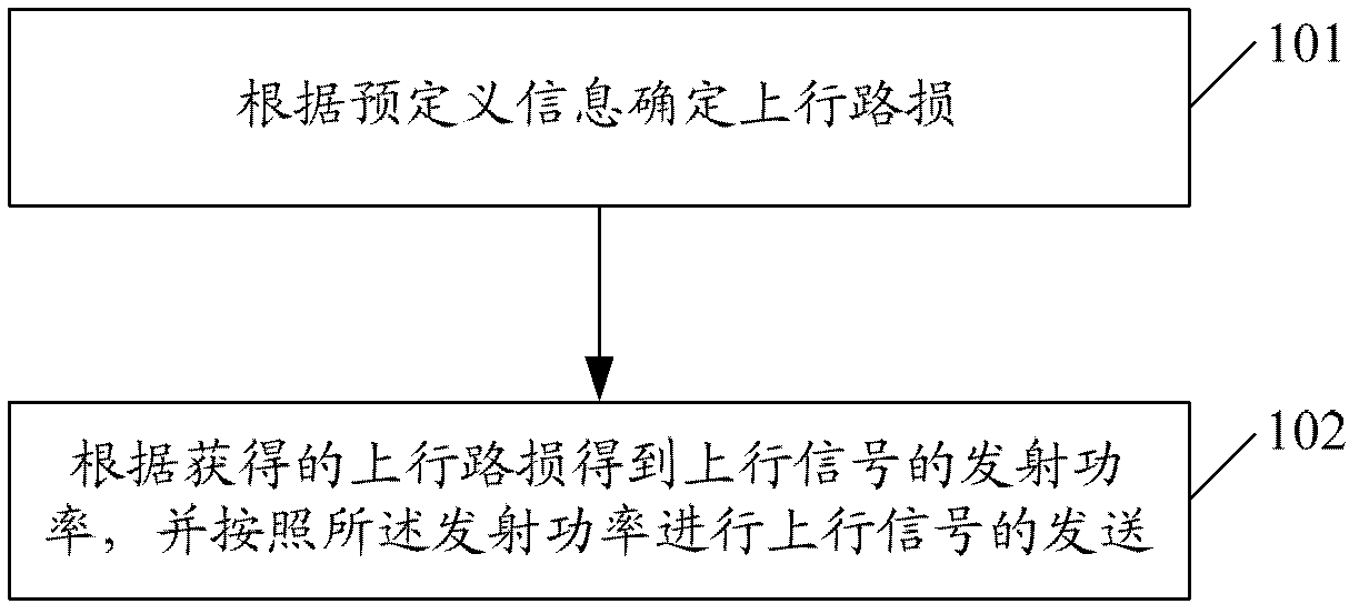
[0092] In Embodiment 1-1, the predefined information includes CSI-RS and signal type, and the determination of the uplink path loss according to the predefined information is: the path loss value measured from the same fixed CSI-RS port is used as the PUCCH, PUSCH and the estimated value of the SRS uplink path loss; where the fixed CSI-RS port can be any one of ports 15 to 22 or a fixed one, for example, port 15 is fixed.

[0093] For ease of description, embodiment 1-1 only takes PUSCH as an example, and the calculation formula of the channel transmit power can be:

[0094] P PUSCH , c ( i ) = min P CMAX , c ( ...

Embodiment 1-2

[0098] In Embodiment 1-2, the predefined information includes CSI-RS and signal type, and the determination of the uplink path loss according to the predefined information is: the path loss value measured from the same CSI-RS port is used as the PUCCH, PUSCH and An estimated value of SRS uplink path loss, wherein the CSI-RS port may be port 15 configured through high-level signaling.

[0099] For ease of description, Embodiment 1-2 only takes PUSCH as an example, and the calculation formula of its channel transmission power can be:

[0100] P PUSCH , c ( i ) = min P CMAX , c ( i ) ...


PUM


Abstract

The invention provides an uplink signal sending method. The uplink signal sending method comprises confirming uplink path losses according to pre-defined information, obtaining transmitting power of uplink signals according to the obtained uplink path losses, and sending the uplink signals according to the transmitting power. The invention also provides an uplink signal sending device. According to the uplink signal sending device, the uplink path losses are confirmed in combination with the pre-defined information, the power of the uplink signals is obtained according to the confirmed uplink path losses, the uplink signals are transmitted, different requirements for the transmitting power of the uplink channels under different application scenarios are fully met, the uplink path losses are confirmed by further utilizing CSI-RSs (cell state information reference signals), the capability of open-loop power control is improved, and accurate control of the uplink channels is achieved.

Description

technical field [0001] The present invention relates to the field of mobile communication, in particular to an uplink signal sending method and device. Background technique [0002] The uplink physical channels of the Long Term Evolution (LTE) system include Physical Random Access Channel (Physical Random Access Channel, PRACH), Physical Uplink Shared Channel (Physical Uplink Shared Channel, PUSCH), Physical Uplink Control Channel (Physical Uplink Control Channel) Channel, PUCCH). The LTE uplink adopts a single-carrier Orthogonal Frequency Division Multiplexing (Orthogonal Frequency Division Multiplexing, OFDM) technology, and reference signals and data are multiplexed together in a Time Division Multiplexing (Time Division Multiplexing, TDM) manner. The uplink reference signal includes a demodulation reference signal (Demodulation Reference Signal, DM-RS) and a measurement reference signal (Sounding Reference Signal, SRS). [0003] Since the LTE uplink adopts Single Carri...

Claims


Application Information

Patent Timeline
Patent Type & Authority Applications(China)
IPC IPC(8): H04W52/14H04W52/18
CPCH04W52/242
Inventor 任璐戴博林志嵘夏树强
Owner ZTE CORP
Why Eureka
Try Eureka