
Demolding method and device for end plate of side plate of bilateral pre-tensioned pre-stressed concrete track plate

A demoulding device, track plate technology, applied in the direction of unloading device, manufacturing tools, etc., can solve the problems of partial cracks in the anchor hole, no extensive reports found, difficulty in controlling synchronization and levelness, etc.

Inactive Publication Date: 2013-07-24
欧阳炎
View PDF11 Cites 2 Cited by
  • Summary
  • Abstract
  • Description
  • Claims
  • Application Information

AI Technical Summary

Problems solved by technology

The defect of this prior art is that: in order to prevent the anchor material from falling off during the service of the track plate, an annular groove is usually engraved on the forming part of the anchor hole on the mold, and a rubber sealing ring is added to anchor the track plate after demoulding. The hole part leaves an annular groove, but because it is difficult to control the synchronization and levelness during demoulding, it is easy to cause visible micro cracks in the anchor hole part
[0015] However, so far, there is no extensive report on the demoulding technology of the above-mentioned two-way pretensioned prestressed concrete track slab side plate end plate, and there is a need for improvement.

Method used


Image

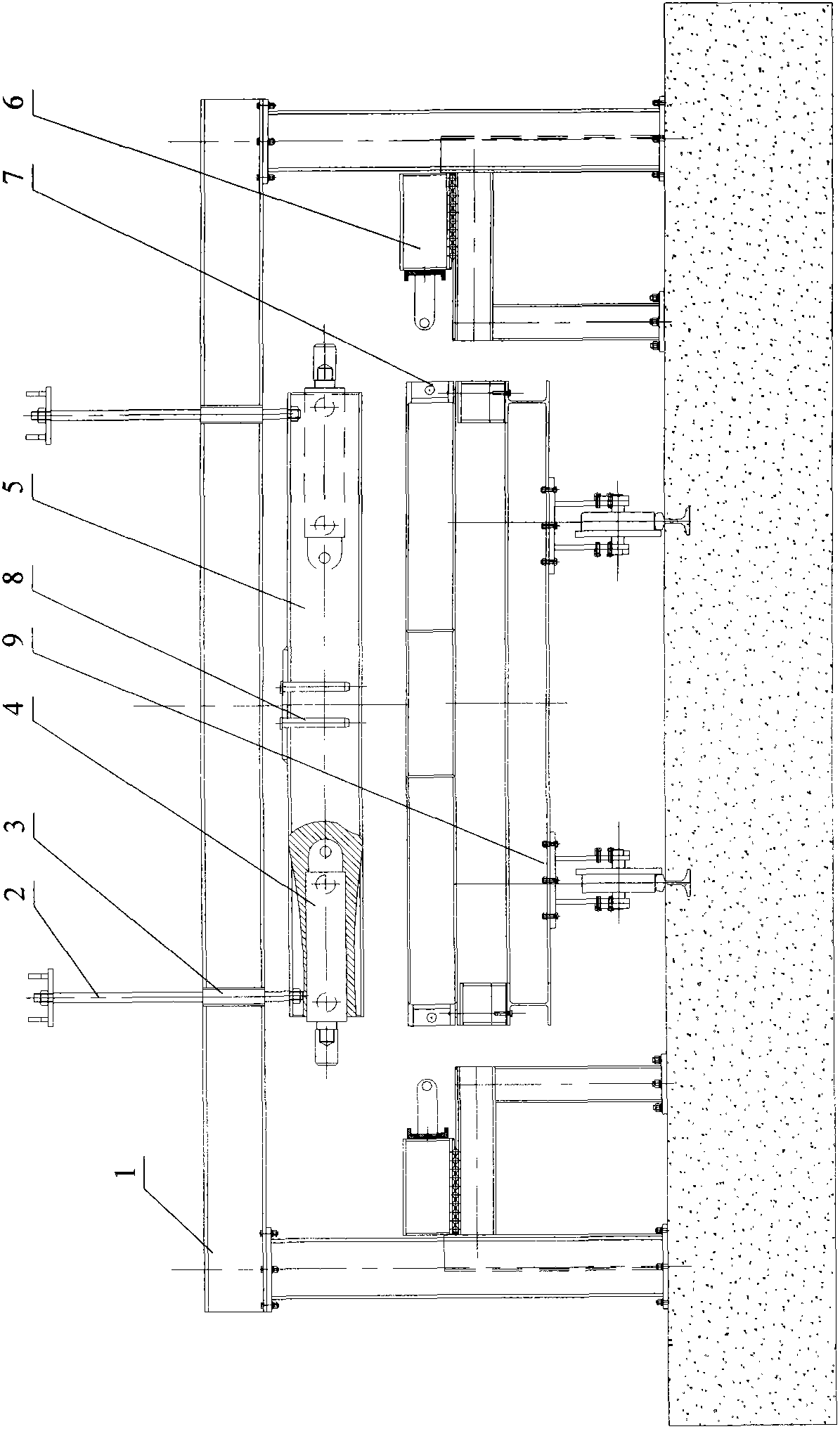
  • Demolding method and device for end plate of side plate of bilateral pre-tensioned pre-stressed concrete track plate
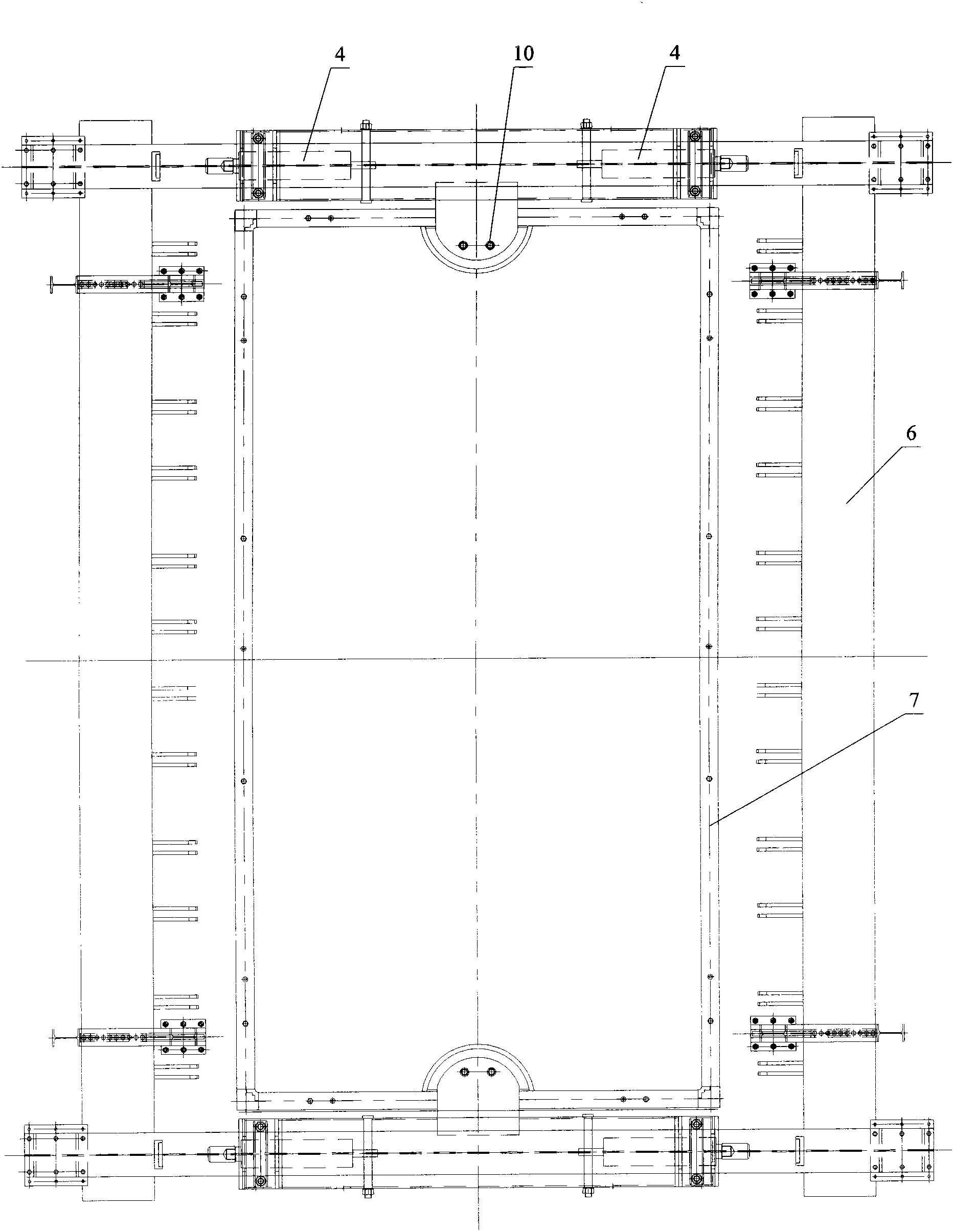
  • Demolding method and device for end plate of side plate of bilateral pre-tensioned pre-stressed concrete track plate
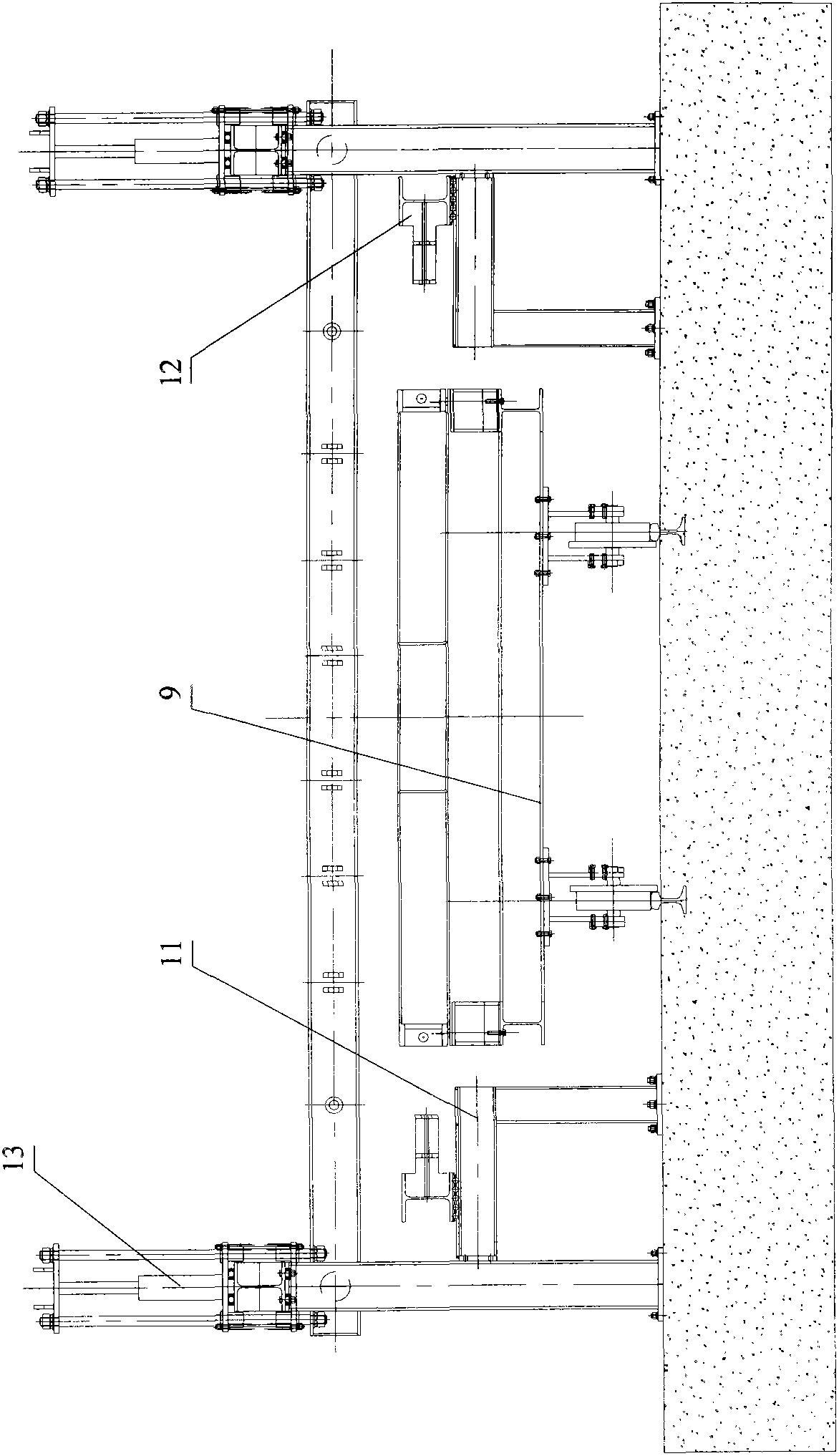
  • Demolding method and device for end plate of side plate of bilateral pre-tensioned pre-stressed concrete track plate

Examples


Embodiment Construction

[0070] The demoulding device and method of the present invention will be described in detail below with reference to the accompanying drawings and specific embodiments, so as to understand the features, details and advantages of the present invention more clearly and completely. It should be pointed out that those skilled in the art can easily understand that the following examples are only preferred exemplary examples given to facilitate the understanding of the present invention, and are not meant to limit the present invention in any way. On the contrary, on the basis of reading the present invention, those skilled in the art can make any modifications or changes to the following embodiments, and the features in different embodiments can be changed or combined as required. It should be understood that the present invention is not limited to the specific structures, devices, methods, etc. described and shown herein.

[0071] As mentioned above, the demoulding device of the t...


PUM


Abstract

The invention discloses a demolding device for an end plate of a side plate of a bilateral pre-tensioned pre-stressed concrete track plate. The demolding device comprises a side plate demolding device and an end plate demolding device which are used separately or together, and a control system, wherein the side plate demolding device and the end plate demolding device are provided with driving mechanisms which are connected with the control system respectively; and the side plate demolding device and the end plate demolding device work simultaneously or in sequence under the control of the control system, so that the side plate and / or the end plate is separated from the track plate at one time. The invention further relates to a demolding method for the end plate of the side plate of the bilateral pre-tensioned pre-stressed concrete track plate using the demolding device. Preferably, the side plate demolding device and the end plate demolding device are arranged integrally into an integral side plate and end plate demolding device, so that the side plate and the end plate can be separated conveniently and efficiently in sequence or simultaneously. According to the demolding method and the demolding device, the side plate and / or the end plate can be separated conveniently and reliably at one time, so that the appearance of a product is ensured, and the production efficiency is increased.

Description

technical field [0001] The invention relates to a demoulding method and device for a bidirectional pretensioned prestressed concrete track slab side plate end plate, and belongs to the field of manufacturing technology and equipment of high-speed railway ballastless track slabs. Background technique [0002] At present, the high-speed railways in the world mainly use Japanese I-type track slabs and German II-type track slabs. [0003] Japan's I-type track plate is produced by the post-tensioning production process of a single mold. The steel rod is fixed on the side plate by a nut, and the rubber sleeve is used to seal the steel rod and the side plate. The small number of rods and the elasticity of the rubber make it easy to remove the side panels. The defect of this prior art is that: in order to prevent the anchor material from falling off during the service of the track plate, an annular groove is usually engraved on the forming part of the anchor hole on the mold, and a...

Claims


Application Information

Patent Timeline
IPC IPC(8): B28B13/04
Inventor 欧阳炎
Owner 欧阳炎
Learn More