
Strain strengthening storage tank

A strain strengthening, storage tank technology, applied in the direction of container, packaging, transportation and packaging, can solve the problem of residual liquid in the storage tank, and achieve the effect of low drainage cost and good drainage effect.

Inactive Publication Date: 2013-07-24
ZHANGJIAGANG HANJUNG CIT CO LTD
View PDF10 Cites 0 Cited by
  • Summary
  • Abstract
  • Description
  • Claims
  • Application Information

AI Technical Summary

Problems solved by technology

[0003] The technical problem to be solved by the present invention is to provide a strain strengthened storage tank. The structure of the storage tank solves the problem of residual liquid in the storage tank after the strengthening experiment is completed, so that the liquid in the storage tank can be completely discharged

Method used


Image

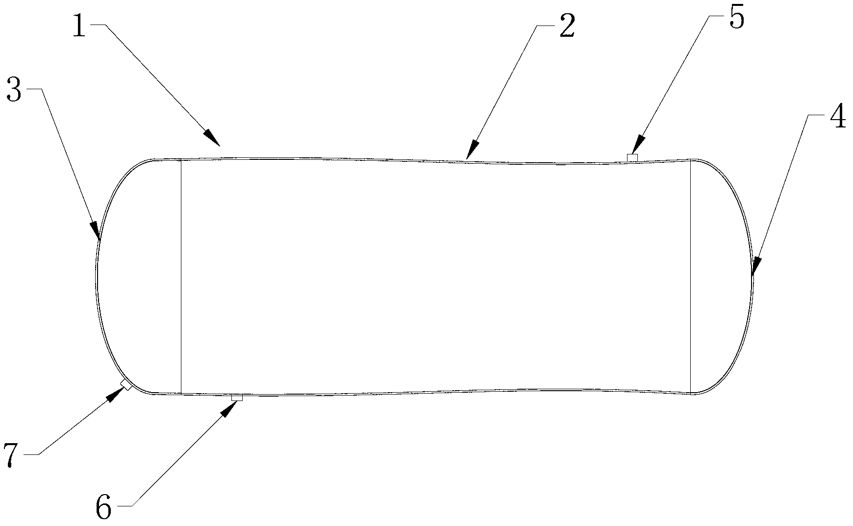
  • Strain strengthening storage tank

Examples


Embodiment Construction

[0017] The strain-strengthened storage tank 1 of the present invention will be further described in detail through specific examples below.

[0018] The directions in this example are up and down based on the state of strain-strengthened storage tanks in normal use. The mentioned inner groove head refers to the head without lining ring, and the outer groove head refers to the head with lining ring. head.

[0019] Such as figure 1 As shown, a strain strengthening storage tank 1, the storage tank 1 includes a cylinder body 2 and a head, the head includes an inner groove head 3 and an outer groove head 4, the upper part of the cylinder body 2 and the lower part are respectively provided with an exhaust port 5 and a first liquid discharge port 6, and the lower part of the inner beveled head 3 is also provided with a second liquid discharge port 7, and the outer beveled head 4 is lifted upwards to form 15 degrees with the ground. °-20°, the second drain port 7 is located at the l...


PUM


Abstract

The invention discloses a strain strengthening storage tank which comprises a barrel body and a seal head. The seal head comprises an inner groove seal head and an outer groove seal head. An air outlet is arranged at the upper portion of the barrel body, and a first liquid outlet is arranged at the lower portion of the barrel body. A second liquid outlet is arranged at the lower portion of the inner groove seal head. When liquid drainage is conducted, the storage tank is at a horizontal position, partial liquid in the storage tank flows out of the first liquid outlet, when no liquid flows out of the first liquid outlet, one end of the outer groove seal head is suspended by a certain angle, the liquid in the storage tank flows out of the second liquid outlet, the liquid drainage is carried out unceasingly until the liquid in the storage tank is completely drained, the fact of no liquid residue in the storage tank is ensured, and the strain strengthening storage tank is low in cost and good in liquid drainage effect.

Description

technical field [0001] The invention relates to a strain strengthened storage tank. Background technique [0002] For the currently used strain intensified storage tanks, a process exhaust port and a process liquid discharge port are respectively set at the highest point and the lowest point of any circumference of the cylinder during the intensification test. After the intensification test is completed, the process exhaust port and process The liquid discharge port is used to empty the liquid in the cylinder. Since the deformation rate of each section of the cylinder is different after the experiment, it is in the shape of a curve in the axial direction. The position of the process liquid discharge port is not necessarily in the entire storage area. The tank is at the lowest point, so draining from the process drain cannot completely empty the tank. In the same way, the liquid in the storage tank cannot be completely drained by purging through the process exhaust port. Si...

Claims


Application Information

Patent Timeline
IPC IPC(8): B65D88/54B65D90/00
Inventor 高卫
Owner ZHANGJIAGANG HANJUNG CIT CO LTD
Learn More