Three-cavity diaphragm pump comprising main shaft provided with limiting structure

A technology of limiting structure and diaphragm pump, applied in the direction of pumps with flexible working elements, pumps, liquid variable capacity machines, etc., can solve the problems of easy breakage of cylindrical pins, troublesome maintenance, inconvenient production, etc., and improve the connection reliability. , to avoid the effect of large pulling effect and prolong the service life

Inactive Publication Date: 2013-07-24
苏州稼乐植保机械科技有限公司
View PDF3 Cites 0 Cited by
  • Summary
  • Abstract
  • Description
  • Claims
  • Application Information

AI Technical Summary

Problems solved by technology

And because the elastic force of the spring changes continuously during the compression and release process, the reverse force on the cylindrical pin also changes continuously. When the motor rotates at high speed, the change frequency of the force on the cylindrical pin is accelerated. There is no structure in the axial direction that can prevent the spindle from moving forward. When the motor rotates at high speed, the spindle will move back and forth along the axial direction, and the forward and backward movement of the spindle will directly cause the spindle to push the cylindrical pin forward or pull it backward. Cylindrical pin, the cylindrical pin is subjected to the above-mentioned reverse force and the additional push-pull force of the main shaft, which eventually causes the cylindrical pin to be easily broken during use
After the cylindrical pin is broken, the pump needs to be degreased and disassembled, which is very troublesome to repair and causes great inconvenience to production

Method used


Image

  • Three-cavity diaphragm pump comprising main shaft provided with limiting structure

Examples


Embodiment Construction

[0013] Preferred embodiments of the present invention will be described in detail below in conjunction with the accompanying drawings.

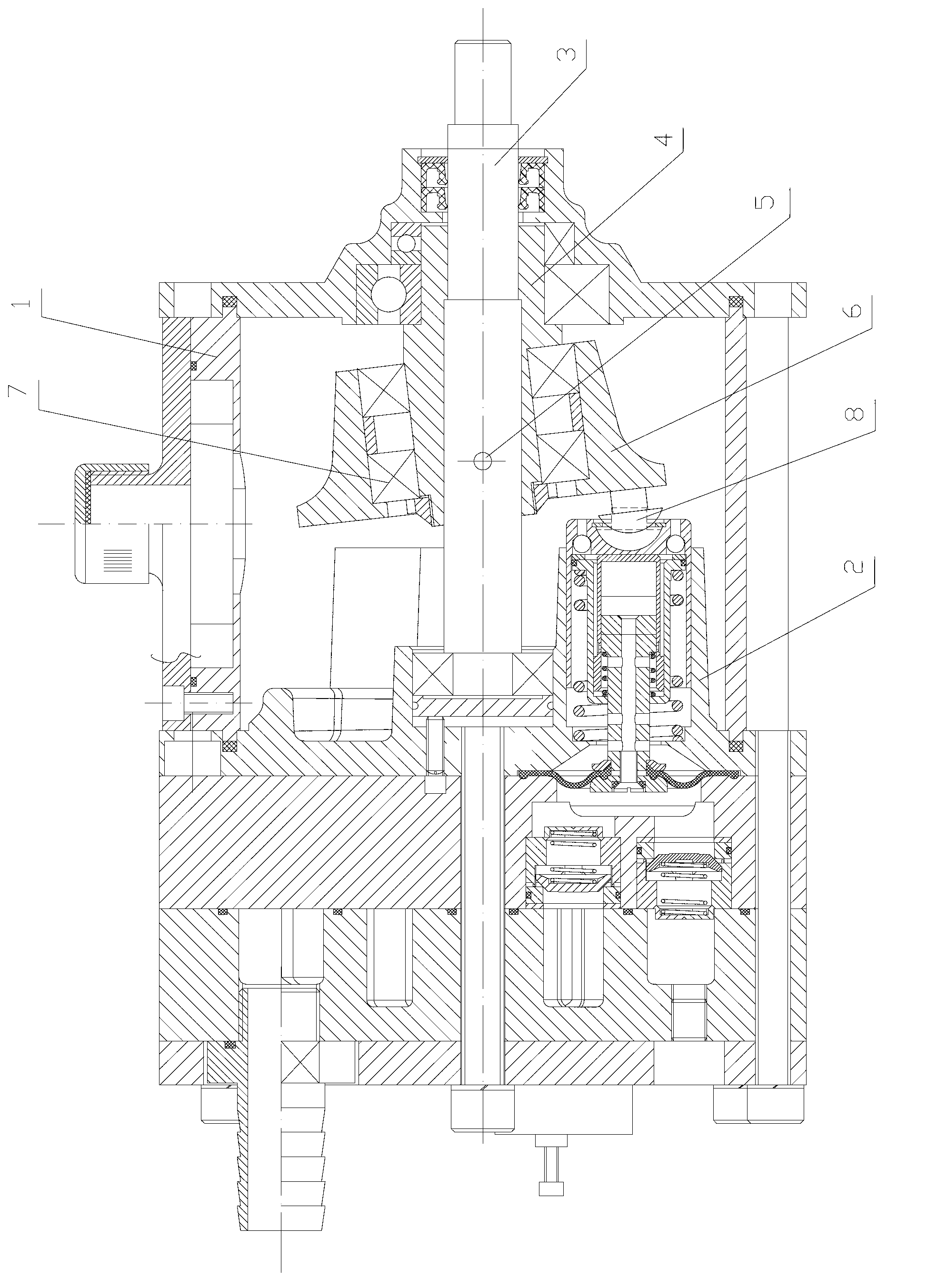
[0014] see figure 1 , the present invention provides a three-chamber diaphragm pump with a limiting structure for the main shaft, which includes a housing 1, a pump body 2 connected to the housing 1, and a main shaft 3 connected to the motor; the main shaft 3 and the eccentric sleeve 4 pass through a cylindrical pin 5 is fixedly connected, the wheel disc 6 is fixedly connected with the eccentric sleeve 4 through the bearing 7; at the same time, the wheel disc 6 is connected with the spherical shaft 8 arranged on the pump body 2, and the main shaft 3 has a device that limits itself along the axial direction. A limit structure for movement outside the housing 1.

[0015] In this embodiment, the position-limiting structure is a stepped structure, the main shaft 3 is a different-diameter structure, and is installed in the eccentric sleeve 4, and...


PUM


Abstract

The invention provides a three-cavity diaphragm pump comprising a main shaft provided with a limiting structure. The three-cavity diaphragm pump comprises a shell, a pump body and the main shaft, wherein the pump body is connected with the shell, and the main shaft is connected with a motor. The main shaft is fixedly connected with an eccentric locking collar through a straight pin, and a turbine disc is fixedly connected with the eccentric locking collar through a bearing. Meanwhile, the turbine disc is connected with a spherical shaft arranged on the pump body, and the main shaft is provided with the limiting structure limiting movement, towards the outside of the shell along the axial direction, of the main shaft. Compared with the prior art, the three-cavity diaphragm pump comprising the main shaft provided with the limiting structure resolves the problem that the straight pin connected with the main shaft and the eccentric locking collar is easy to break in the prior art. The main shaft rotates stably, the main shaft is connected with the eccentric locking collar reliably, and service life of the pump is prolonged.

Description

technical field [0001] The invention relates to a three-chamber diaphragm pump used in plant protection, in particular to a three-chamber diaphragm pump whose main shaft has a limiting structure. Background technique [0002] The applicant discloses a three-chamber diaphragm pump in another Chinese utility model patent CN202468238U, which includes a casing, a pump body connected to the casing, and a water inlet and a water outlet arranged in the pump body. At least two cavities, the main shaft connected with the motor; the main shaft is connected with the eccentric sleeve, and the wheel disc is fixedly connected with the eccentric sleeve through the bearing; at the same time, the wheel disc is connected with the spherical shaft in the cavity, and the spherical shaft passes through the cavity lining The sleeve is connected with the sliding sleeve of the cavity, separated by a cavity spacer in the middle; the hollow driving mandrel is set in the middle of the cavity, the diaph...

Claims


Application Information

Patent Timeline
Patent Type & Authority Applications(China)
IPC IPC(8): F04B43/02
Inventor 陈晓平邱桂生
Owner 苏州稼乐植保机械科技有限公司
Why Eureka
Try Eureka