Modal parameter identification method based on response signal time-frequency joint distribution characteristics

A technology of distribution characteristics and time-frequency combination, applied in measuring devices, instruments, measuring ultrasonic/sonic/infrasonic waves, etc., can solve the problems of noise sensitivity and only processing steady-state signals

Inactive Publication Date: 2013-07-24
BEIJING UNIV OF TECH
View PDF1 Cites 25 Cited by
  • Summary
  • Abstract
  • Description
  • Claims
  • Application Information

AI Technical Summary

Problems solved by technology
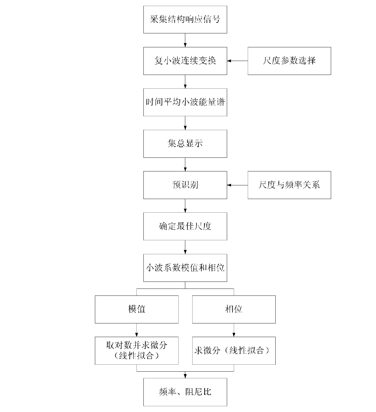
[0004] Traditional modal parameter identification methods are

Method used


Image

  • Modal parameter identification method based on response signal time-frequency joint distribution characteristics
  • Modal parameter identification method based on response signal time-frequency joint distribution characteristics
  • Modal parameter identification method based on response signal time-frequency joint distribution characteristics

Examples


Embodiment 1

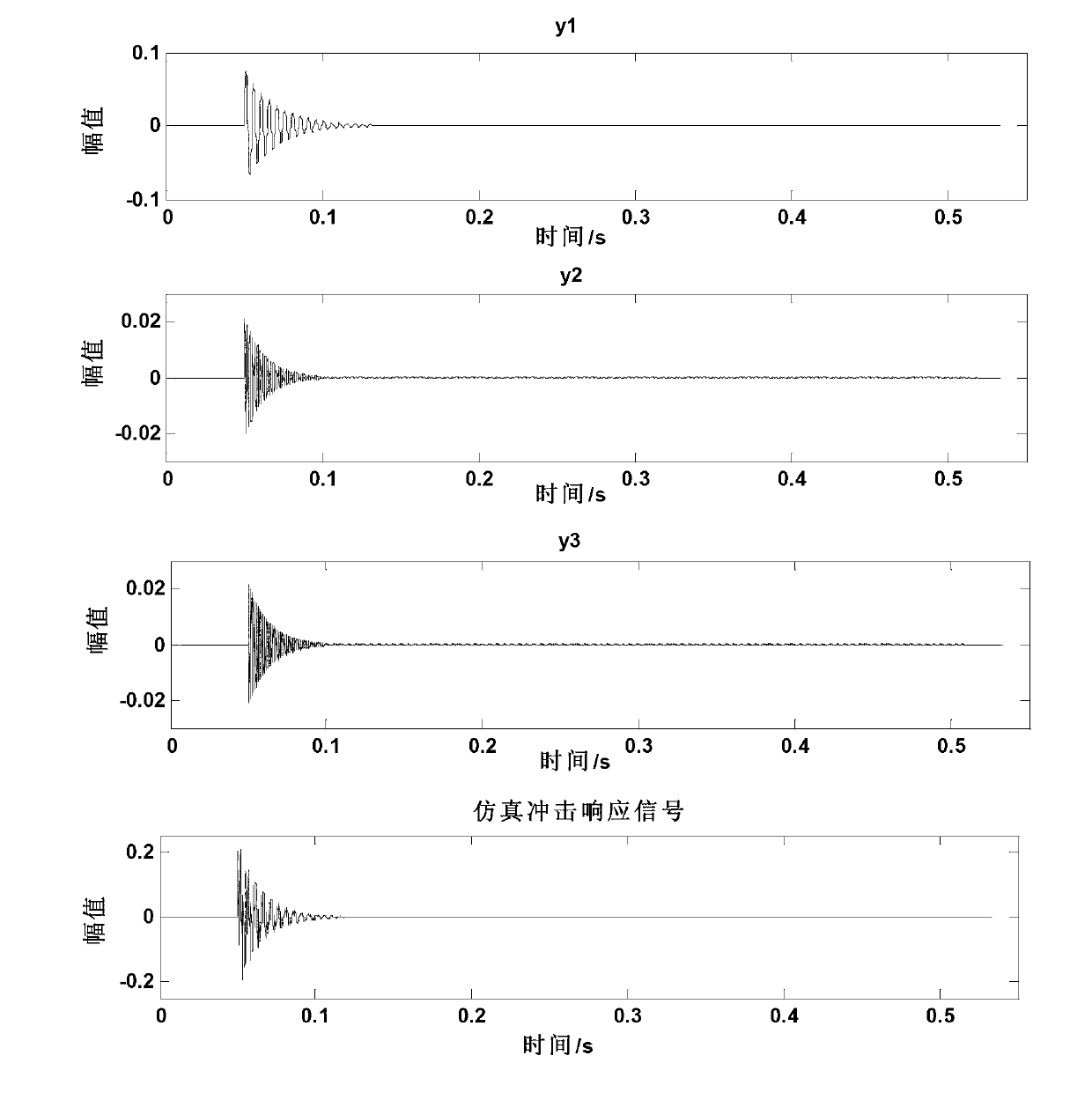
[0066] Embodiment 1: Simulation signal

[0067] Construct the impulse response signal of a single-degree-of-freedom structural system to simulate the response signal of the first three modes of the structure:

[0068] y(t)=ay 1 (t)+by 2 (t)+cy 3 (t)

[0069] where y i (t) represents the shock response signal corresponding to the i-th mode:

[0070] y i ( t ) = e - ζ i 2 π f i t sin 2 π f i t 1 - ζ i 2 , i = 1,2,3

[0071] Let the third order frequencies be f ...

Embodiment 2

[0076] Example 2: Experimental Signal

[0077] In order to verify the effectiveness of the method described in the present invention, the modal experiment of multi-rotor structure has been implemented, and its structure is schematically shown as Image 6 . Structure 2 is the measured rotor structure, Figure 7 is its three-dimensional solid model. The structural material is 45 steel, the elastic modulus is 210GPa, Poisson's ratio is 0.3, and the material density is 7800kg / m 3 . In the test, the hammer is used as the pulse excitation source to excite the vibration, and the piezoelectric acceleration sensor is used to pick up the response signal. The number of measuring points is 20, the sampling frequency is set to 3200Hz, and the sampling length is 1024.

[0078] Because the modal parameter range of the actual signal is unknown, the value range can be selected in advance when selecting the scale parameter, and then the scale parameter can be adjusted according to the corr...


PUM

PropertyMeasurementUnit
Elastic modulusaaaaaaaaaa
Densityaaaaaaaaaa

Abstract

The invention relates to a modal parameter identification method based on response signal time-frequency joint distribution characteristics. According to the modal parameter identification method based on the response signal time-frequency joint distribution characteristics, signal analysis and structural modal parameter identification are carried out directly through a structural vibration response. The modal parameter identification method based on the response signal time-frequency joint distribution characteristics comprises the steps of firstly carrying out complex wavelet continuous transformation on a structural response signal, obtaining energy distribution characteristics of various wavelet transformation domains (a real domain, a virtual domain, a modal domain and a phase domain), obtaining a time average wavelet energy spectrum through a wavelet transformation coefficient, therefore carrying out quantification on selection of model orders and the scale corresponding to each order modality, on the basis, obtaining the optimum scale required by parameter identification, achieving pre-identification of modal frequency through the corresponding relation of the scale and the frequency, finally extracting a wavelet transformation coefficient slice at the specific scale, carrying out linear fitting through an amplitude value and a phase component, and achieving structural identification of inherent frequency and a damping ratio. As simulation and experiment results show, even if an external incentive function is not included, accurate identification of structural modal parameters can be achieved through the modal parameter identification method based on the response signal time-frequency joint distribution characteristics.

Description

technical field [0001] The invention belongs to the field of modal parameter identification, and in particular relates to a modal parameter identification method based on complex wavelet continuous transformation, which uses impulse response signals to identify modal frequencies and damping ratios. Background technique [0002] Modal parameter identification is to accurately estimate the modal parameters of the vibration system from the test signal, including modal natural frequency, modal damping ratio, etc. [0003] The traditional modal parameter identification methods are divided into time-domain method and frequency-domain method, which cannot use the time-domain and frequency-domain information of the data at the same time, so the accuracy of parameter identification is limited. In addition, the traditional parameter identification method must measure the excitation signal and the response signal at the same time, but in practical engineering applications, especially f...

Claims


Application Information

Patent Timeline
IPC IPC(8): G01H17/00
Inventor 张建宇杨洋马金宝胥永刚张随征刘鑫博
Owner BEIJING UNIV OF TECH
Why Eureka
Try Eureka