Automatic torsion testing machine

A torsion testing and automatic technology, applied in the direction of measuring devices, power measurement, instruments, etc., can solve the problems of fatigue and low efficiency of the staff, and achieve the effect of improving work efficiency, reducing operation fatigue, and improving the advanced level

Inactive Publication Date: 2013-07-24
SUZHOU NETABHAPE COMPOSITE MATERIALS
6 Cites 2 Cited by

AI-Extracted Technical Summary

Problems solved by technology

[0002] Most of the existing torsion testing machines are manually tested, and the tool is a torsion hand, which uses manpower t...

Abstract

The invention discloses an automatic torsion testing machine. The automatic torsion testing machine comprises a first table support, a second table support, a third table support, a fourth table support and stand bars, wherein the framework of the whole torsion testing machine is formed by the first table support, the second table support, the third table support and the fourth table support, the stand bars are installed on the bottom corners of the framework, a working table is arranged above the third table support and the fourth table support, a second part detecting sensor is installed above the third table support and on the working table, and a first part detecting sensor is installed above the fourth table support and on the working table. The automatic torsion testing machine has the advantages that working efficiency is improved, labor intensity of workers is relieved, and the integral advanced level of an enterprise can be improved.

Application Domain

Work measurementTorque measurement

Technology Topic

Industrial engineering

Image

  • Automatic torsion testing machine
  • Automatic torsion testing machine

Examples

  • Experimental program(1)

Example Embodiment

[0013] Hereinafter, the present invention will be described in detail with reference to the accompanying drawings and the embodiments.
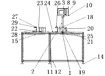
[0014] Reference figure 1 As shown, an automatic torsion testing machine includes a first workbench support 11, a second workbench support 12, a third workbench support 15, a fourth workbench support 25, and feet 14, the first workbench support 11 , The second workbench support 12, the third workbench support 15 and the fourth workbench support 25 constitute the frame of the entire mechanism, the feet 14 are installed on the bottom corners of the frame, the third workbench support 15 and the Above the fourth workbench support 25 is a workbench 24, above the third workbench support 15 and on the workbench 24 is installed a second part detection sensor 27, in the fourth work A first part detection sensor 26 is installed above the table support 25 and on the working table 24.
[0015] Further, the second part detection sensor 27 is fixed on the workbench 24 through a part detection sensor bracket 28, and a part detection is connected below the second part detection sensor 27 The sensor tray 29 is provided with a second torsion tool 23 beside the second part detection sensor 27, and a second coupling 22 is also installed under the second torsion tool 23.
[0016] Further, a first torsion tool 18 is installed next to the first part detection sensor 26, and the first torsion tool is fixed on the worktable 24 by a torsion tool bracket 21, and the inside of the torsion tool bracket 21 A spline sleeve tooling 20 is installed at the top of the spline sleeve tooling 20. Below the spline sleeve tooling 20 is a second coupling 19, the second coupling 19 is fixed on the worktable 24 through the bearing 1, and the first Above a torsion tool 18 is the electric axle box bracket 2. The electric axle box bracket 2 is connected to the electric control box 8 through the bracket bracket 3. The leftmost side of the electric control box 8 is the electric control box rear cover 10, A touch screen 9 is also arranged inside the electric control box 8.
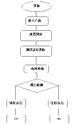
[0017] Operation process of the present invention:
[0018] 1. The operator puts in the product and the test run starts;
[0019] 2. The motor rotates at the set angle for torque test;
[0020] 3. The torque reaches the set value, the test is completed, and the green light is on;
[0021] 4. If the torque does not reach the set value, the test is over and the red light is on.
[0022] The above are only preferred embodiments of the present invention and are not used to limit the present invention. For those skilled in the art, the present invention can have various modifications and changes. Any modification, equivalent replacement, improvement, etc., made within the spirit and principle of the present invention shall be included in the protection scope of the present invention.

PUM

no PUM

Description & Claims & Application Information

We can also present the details of the Description, Claims and Application information to help users get a comprehensive understanding of the technical details of the patent, such as background art, summary of invention, brief description of drawings, description of embodiments, and other original content. On the other hand, users can also determine the specific scope of protection of the technology through the list of claims; as well as understand the changes in the life cycle of the technology with the presentation of the patent timeline. Login to view more.

Similar technology patents

Report data generating method and system

ActiveCN103473342ASimplify the docking processImprove work efficiency
Owner:BEIJING JOIN CHEER SOFTWARE

Caking fertilizer crushing device for agriculture big data

Owner:安徽众力农业装备科技有限公司

Classification and recommendation of technical efficacy words

  • Reduce operator fatigue
  • Improve work efficiency

Sawing tool for plywood test piece

ActiveCN102554982AImprove operational safetyReduce operator fatigue
Owner:宁波朝露新材料科技有限公司

Chassis drive system control method and device

ActiveCN103273922AReduce operator fatiguehigh degree of automation
Owner:ZOOMLION HEAVY IND CO LTD

Power crimping device and method for crimping building panels

InactiveUS20100077827A1reduce operator fatiguecrimp process easy
Owner:MIC IND INC

Cooperation service platform facing different source data

InactiveCN101174957AImprove management level and qualityImprove work efficiency
Owner:NANJING UNIV OF FINANCE & ECONOMICS

Screw drilling tool, vertical drilling tool testing method and well inclination simulation testing equipment

InactiveCN111594144AReduced height requirementsImprove work efficiency
Owner:DEZHOU UNITED GASOLINEEUM MACHINERY

Method for intelligent automatic identification of transmission circuit parts

Owner:INFORMATION COMM COMPANY STATE GRID SHANDONG ELECTRIC POWER +2

Keyboard spill-proofing mechanism

ActiveUS7030330B2minimize manufacturing costimprove work efficiency
Owner:LITE ON SINGAPORE PTE LTD
Why Eureka
Try Eureka