Cooling system with coolant circulation duct

A coolant and pipeline technology, applied in the field of injection molding, can solve problems such as the inability to guarantee the expansion volume

Active Publication Date: 2013-07-31
STAUBLI FAVERGES SA
View PDF6 Cites 3 Cited by
  • Summary
  • Abstract
  • Description
  • Claims
  • Application Information

AI Technical Summary

Problems solved by technology

Furthermore, such a device does not guarantee that sufficient expansion volume is available for the coolant in the event of failure of said spring

Method used


Image

  • Cooling system with coolant circulation duct
  • Cooling system with coolant circulation duct
  • Cooling system with coolant circulation duct

Examples


Embodiment Construction

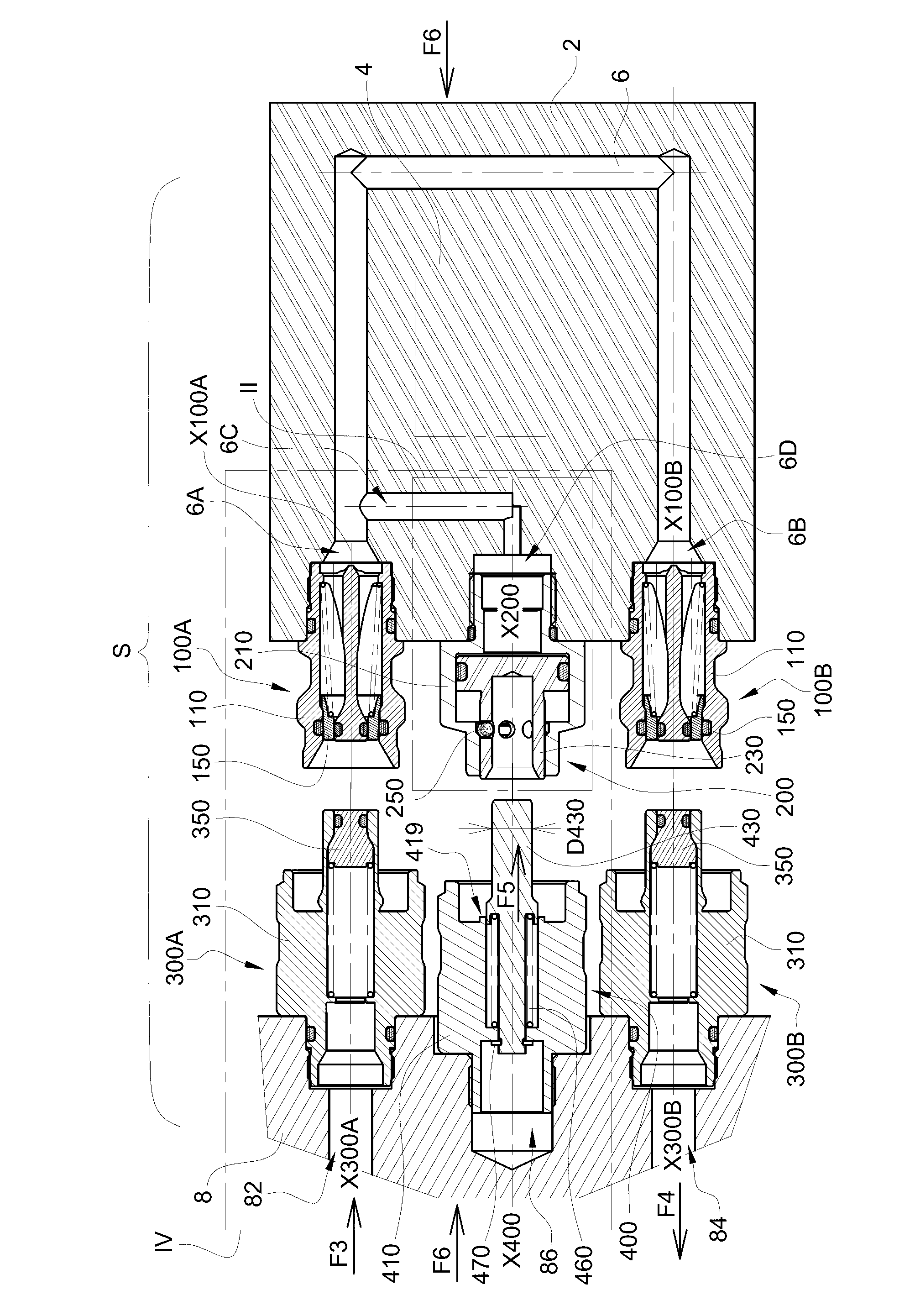
[0029] exist figure 1 In , a heat exchange plate 2 is used to cool electronic devices 4 of the Insulated Gate Bipolar Transistor (IGBT) type or any other components that become hot during operation. Circulation pipes 6 for a coolant such as water or oil are formed in the plate 2 and extend between a first end 6A and a second end 6B, each end being fitted with a connector element 100A or 100B respectively .

[0030] These connector elements 100A and 100B are identical and each comprise a body 110 screwed into a corresponding threaded hole of the corresponding board 2 and inserting a seal 120 . Each body 110 is hollow and defines a central bore 130 within which a push-piece 140 is stationary relative to said body 110 . Said central hole 130 constitutes the internal conduit of the connector element 100A. A closure element or valve 150 is mounted in the central bore 130 and is acted upon by an elastic return spring 160 for springing the closure element 150 back onto the seat 11...


PUM


Abstract

The system (S) has a heat exchange plate (2) comprising a coolant circulation duct (6) equipped with connector elements (100A, 100B), at ends. A maintaining element (400) locks a piston (230) in its retracted position when one of the connector element and a complementary connector element (300A) are coupled. The maintaining element keeps the piston in its retracted position, during separation of the connector element and the complementary element as long as an obturator (150) of the connector element is not in an obturation position of an inner duct of the connector element.

Description

technical field [0001] The invention relates to a system for cooling at least one part of a component, wherein the plate used contains coolant circulation channels. The invention is particularly applicable in the field of temperature control of electronic devices and in the field of injection molding of parts made of synthetic materials, where cooling of the mold is necessary. Background technique [0002] In the case of heat exchange plates designed to cool electronic components, coolant circulation ducts are defined inside said plate and are designed to be connected at both ends to supply ducts, which in turn are connected to a supply of refrigerated coolant And connected to the pipe for the discharge fluid. When the pipes of the board are disconnected from the supply pipes, while the still hot electronics are transferring heat to the coolant confined in the pipes, the coolant itself experiences a rise in temperature with essentially The pressure increases, causing the p...

Claims


Application Information

Patent Timeline
Patent Type & Authority Applications(China)
IPC IPC(8): B29C45/73H05K7/20
CPCF28F2265/12F28F2265/14F28D1/035F28F3/12F28F2265/16F16L37/32H05K7/20272F28F9/0253F28F9/0258F28F7/02F28F27/00F16L37/34F16L37/56
Inventor A-C·蒂贝尔吉安C·迪里厄F·莫雷尔
Owner STAUBLI FAVERGES SA
Why Eureka
Try Eureka