Electromagnetic flowmeter and determinator

An electromagnetic flowmeter and electrode technology, which is applied in the application of electromagnetic flowmeters to detect fluid flow, volume/mass flow generated by electromagnetic effects, etc., can solve problems such as gasket damage, gasket loss of shrinkage space, extrusion, etc.

Inactive Publication Date: 2013-07-31
KK TOSHIBA
View PDF8 Cites 6 Cited by
  • Summary
  • Abstract
  • Description
  • Claims
  • Application Information

AI Technical Summary

Problems solved by technology

At this time, if the electrode member is pushed from the inside of the measurement tube to the outside, the sealing (airtightness) between the electrode member and the measurement tube will be enhanced, but if the electrode member is pushed excessively, there

Method used


Image

  • Electromagnetic flowmeter and determinator
  • Electromagnetic flowmeter and determinator
  • Electromagnetic flowmeter and determinator

Examples


no. 1 approach )

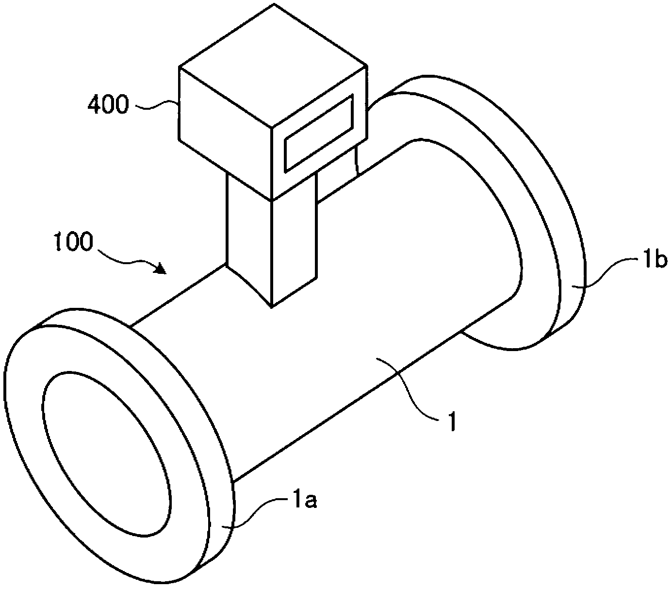
[0017] figure 1 It is an external perspective view of the measurement device of the first embodiment. Such as figure 1 As shown, the measurement device is used to measure the flow rate of a fluid as an object to be measured, and is composed of an electromagnetic flowmeter 100 and a control unit 400 . The electromagnetic flowmeter 100 is provided with: a measuring tube 1 through which a fluid as an object to be measured flows, and a pair of electrode members 2 facing the peripheral wall of the measuring tube 1 (see figure 2 ). In addition, flanges 1a and 1b for connecting to piping not shown are provided at both ends of the measuring tube 1 . The control unit 400 is integrally formed with the electromagnetic flowmeter 100 , and is usually installed above the measuring tube 1 of the electromagnetic flowmeter 100 .

[0018] Next, an outline of the operation of the measurement device will be described. In the measuring device, a magnetic field is formed inside the measuring ...

no. 2 approach )

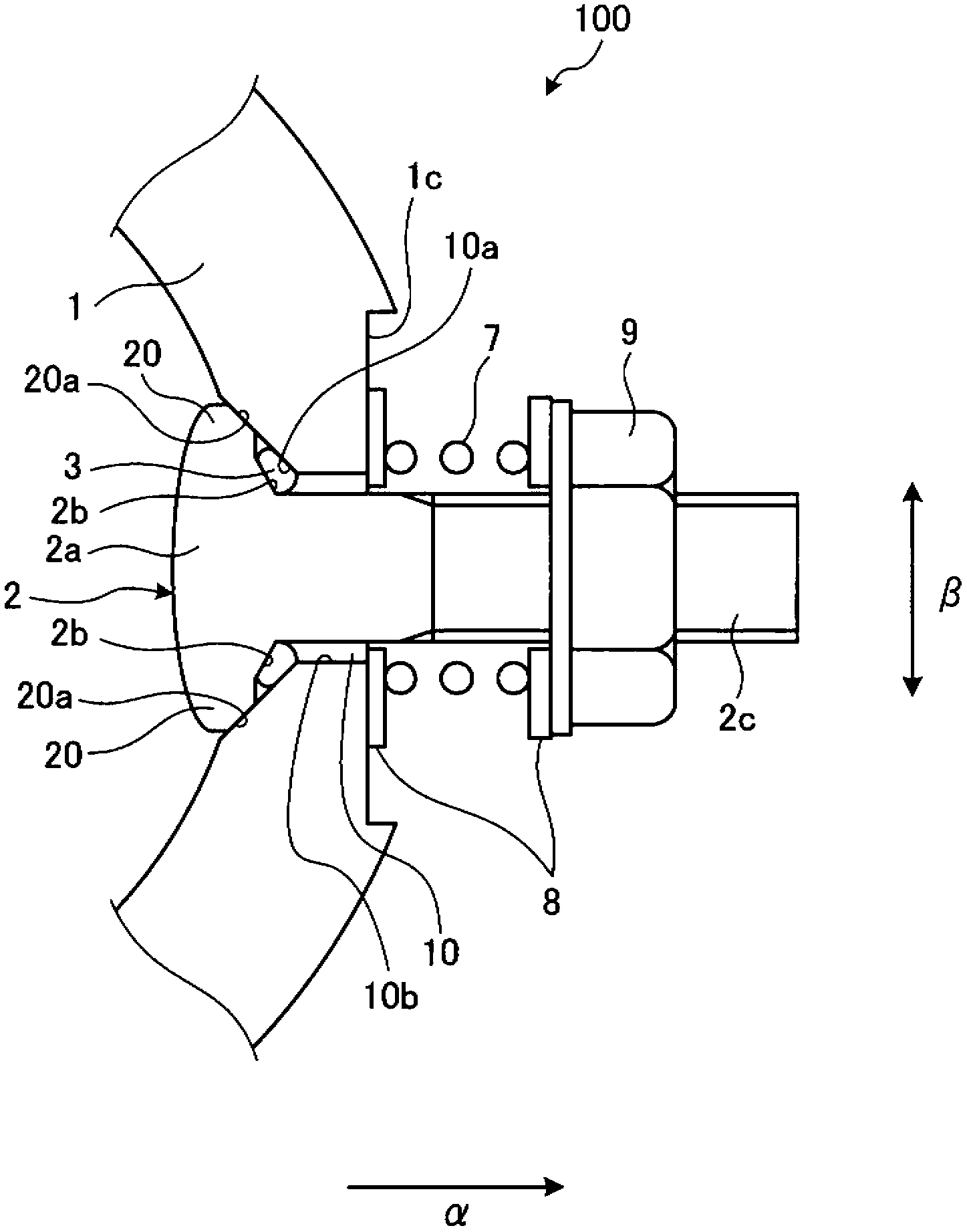
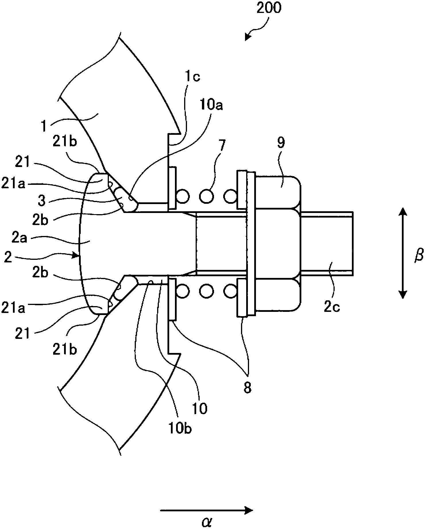
[0035] The electromagnetic flowmeter of the first embodiment is configured such that the electrode member 2 is provided with a protruding portion 20 having an inclined surface 20a in a direction intersecting the direction from the inside of the measuring tube 1 toward the outside (see figure 2 ). On the other hand, in the electromagnetic flowmeter of this embodiment, the electrode member is formed with a protruding portion that does not have the inclined surface 20a.

[0036] image 3 It is a sectional view of an electrode and its peripheral part of the electromagnetic flowmeter of the second embodiment. The electromagnetic flowmeter 200 of this embodiment mainly includes a measuring tube 1 , an electrode member 2 , a gasket 3 , a spring 7 , a spacer 8 , and a nut 9 . Here, the structures and functions of the measuring tube 1 , the washer 3 , the spring 7 , the spacer 8 , and the nut 9 are the same as those of the first embodiment, and therefore description thereof will be ...

no. 3 approach )

[0047] The electromagnetic flowmeter of the first embodiment is configured such that the electrode member 2 is provided with a protruding portion 20 having an inclined surface 20a in a direction intersecting the direction from the inside of the measuring tube 1 toward the outside (see figure 2 ). On the other hand, in the electromagnetic flowmeter of the present embodiment, the electrode member is formed with a protruding portion protruding in a direction from the inside of the measuring tube toward the outside.

[0048] Figure 4 It is a sectional view of an electrode and its peripheral part of the electromagnetic flowmeter of the third embodiment. The electromagnetic flowmeter 300 of this embodiment mainly includes a measuring tube 1 , an electrode member 2 , a gasket 3 , a spring 7 , a spacer 8 , and a nut 9 . Here, the structures and functions of the measuring tube 1 , the washer 3 , the spring 7 , the spacer 8 , and the nut 9 are the same as those of the first embodime...


PUM


Abstract

The invention provides an electronmagnetic flowmeter and a determinator, which can ensure tightness. Moreover, the sealing component is not damaged by squeezing, and can not be squeezed out between the electrode component and the determinator. The electromagnetic flowmeter comprises a determinator (1), an electrode component (2), spring (7) and a gasket (3). The determinator is provided with a tubular peripheral wall with a through-hole (10), and the inner part of the peripheral wall has fuild, and the inner peripheral surface of the through-hole is provided with an inclined plane (10a). The electrode component is inserted in the through-hole, and has an inclined plane (1b), which is opposited to the inclined plane (10a), and the diameter is reduced along the inner part of the periphearl surface to the outside; an a protruding part (20), which is protruded from the inclined surface in a ring shape, and is against the inclined surface, and a gap is provided between the inclined surfaces. The spring (7) pushes the electrode component to the outside from the inner part of the peripheral surface. The gasket is a ring shaped component, and is clamped in the gap between inclined surfaces in a pressed state.

Description

[0001] This application is based on Japanese Patent Application No. 2012-012908 filed on January 25, 2012 and enjoys the priority of this earlier application. This application incorporates the entire content of this earlier application by referring to it. technical field [0002] Embodiments of the present invention relate to an electromagnetic flowmeter and a measurement device. Background technique [0003] Conventionally, as a device for measuring the state of an object to be measured as a physical quantity, for example, an electromagnetic flowmeter for measuring the flow rate of a liquid and a thermometer for measuring the temperature of a liquid are known. In this electromagnetic flowmeter, a magnetic field is generated in a measuring tube by passing a current through a coil. Then, the flow rate is measured by detecting an electromotive force generated in a direction perpendicular to the magnetic field in proportion to the flow velocity of the liquid flowing in the mea...

Claims


Application Information

Patent Timeline
IPC IPC(8): G01F1/58
Inventor 饭岛拓也
Owner KK TOSHIBA
Why Eureka
Try Eureka