
A communication control method, system and device for building equipment

A technology of communication control and building equipment, applied in the direction of transmission system, electrical components, etc., can solve the problems of poor access, labor-intensive and waste of resources, etc.

Inactive Publication Date: 2016-04-27
ANKE SMART CITY TECH PRC
View PDF4 Cites 0 Cited by
  • Summary
  • Abstract
  • Description
  • Claims
  • Application Information

AI Technical Summary

Problems solved by technology

[0004] The embodiment of the present invention provides a communication control method, system and device for building equipment, aiming to solve the problem that the prior art consumes a lot of manpower and wastes resources, but often fails to obtain good results

Method used


Image

  • A communication control method, system and device for building equipment
  • A communication control method, system and device for building equipment

Examples


Embodiment 1

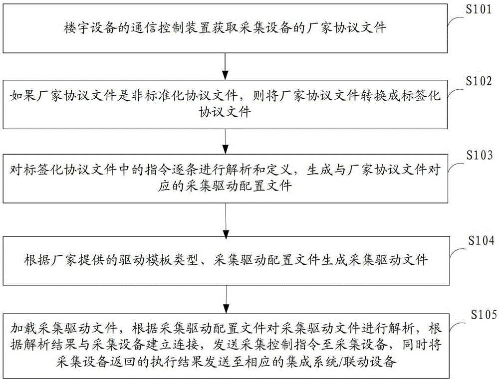
[0049] figure 1The implementation flow of the communication control method for building equipment provided by Embodiment 1 of the present invention is shown, and the details are as follows:

[0050] In step S101, the communication control device acquires the manufacturer's protocol file of the acquisition device.

[0051] In this embodiment, the communication control device is usually installed between the integrated system / linkage device and the weak current collection device / weak electronic system, and the manufacturer's customized collection device is generally located in the weak current collection device / weak electronic system. The connection between the communication control device and the manufacturer's customized acquisition equipment supports TCP / IP mode, serial port mode and 485 mode. After the communication control device establishes a connection with the acquisition equipment, the manufacturer's protocol file of the acquisition equipment can be obtained.

[0052] ...

Embodiment 2

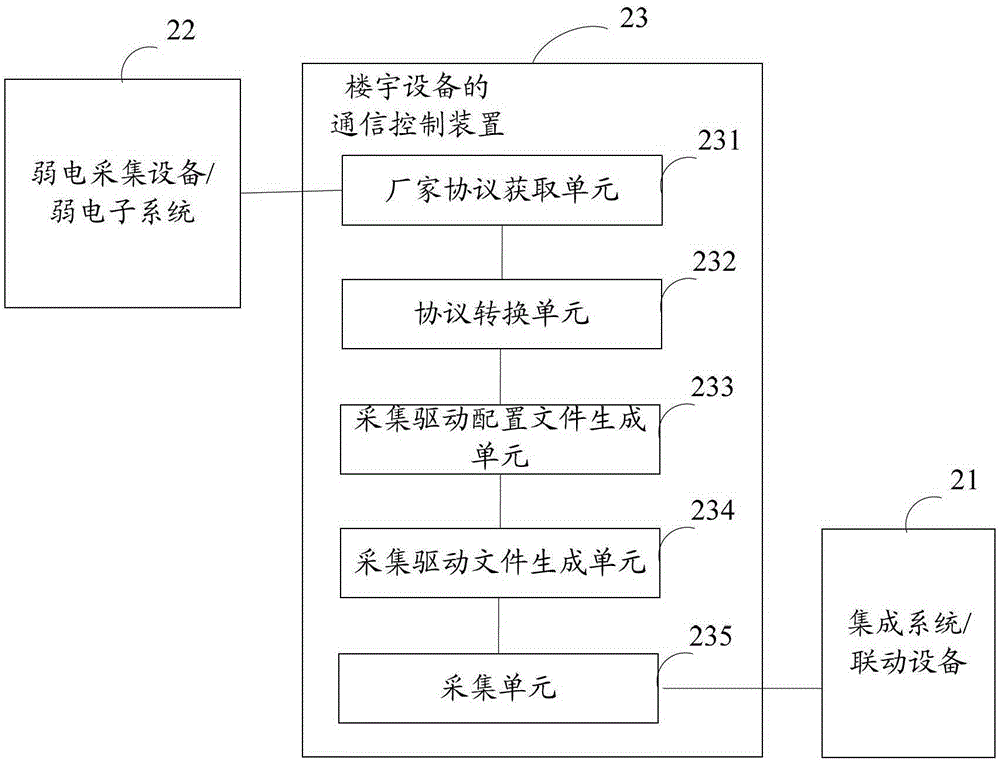
[0087] figure 2 A specific structural block diagram of the communication control system for building equipment provided by Embodiment 2 of the present invention is shown. For convenience of description, only parts related to the embodiment of the present invention are shown. The system includes: integrated system / linkage equipment 21 and weak current acquisition equipment / weak electronic system 22, the acquisition equipment 221 is located in the weak current acquisition equipment / weak electronic system 22, and the system also includes: installed in the integrated system / linkage equipment 21 and weak current acquisition equipment Communication control device 23 for building equipment between / weak electronic system 22 .

[0088] Wherein, the communication control device 23 of building equipment includes: a manufacturer's protocol acquisition unit 231 , a protocol conversion unit 232 , a collection driver configuration file generation unit 233 , a collection driver file generat...


PUM


Abstract

The invention is applicable to the field of automatic control and weak current intelligent integration, and provides a communication control method, a communication control system and a communication control device for building equipment. The communication control method comprises the following steps: firstly, converting a non-standardized protocol file of acquisition equipment into a labeled protocol file; secondly, analyzing and defining commands in the labeled protocol file one by one to generate an acquisition drive configuration file corresponding to the non-standardized protocol file provided by a manufacturer; thirdly, according to the type of a drive template and the acquisition drive configuration file which are provided by the manufacturer, generating an acquisition drive file; and finally, loading the acquisition drive file, analyzing the acquisition drive file according to the acquisition driving configuration file, establishing connection with the acquisition equipment according to an analysis result, sending an acquisition control command to the acquisition equipment, and sending an execution result returned by the acquisition equipment to a corresponding integrated system / linkage device by the communication control device. Through the communication control method, the communication control system and the communication control device, the development cost is saved and the project implementing efficiency is improved.

Description

technical field [0001] The invention belongs to the field of building equipment automation control and weak current intelligent integration, and in particular relates to a communication control method, system and device for building equipment. Background technique [0002] At present, with the continuous development of the economy, the demand for intelligent building control equipment is increasing, so higher requirements are put forward for intelligent building, and the construction and management of intelligent building control equipment become more and more important . [0003] Due to the development of demand, people's requirements for life and space are also constantly developing, and higher and higher business requirements for refinement and comfort are put forward. For example, for the light sensor, people require to be able to receive the intensity index of light; the temperature sensor and the humidity sensor can collect the temperature and humidity of a closed spa...

Claims


Application Information

Patent Timeline
Patent Type & Authority Patents(China)
IPC IPC(8): H04L29/06H04L29/08
Inventor 邱洪波郑文炎王栋云赵建吉
Owner ANKE SMART CITY TECH PRC
Learn More