
Pneumatic servo focusing mechanism

A focusing device and fine-tuning screw technology, applied in welding equipment, laser welding equipment, metal processing equipment, etc., can solve the problems of high cost, low adjustment efficiency, inconvenient operation, etc., and achieve low processing and manufacturing costs, convenient use, and excellent structure simple effect

Active Publication Date: 2016-01-27
SUZHOU LEAD LASER TECH
View PDF7 Cites 0 Cited by
  • Summary
  • Abstract
  • Description
  • Claims
  • Application Information

AI Technical Summary

Problems solved by technology

The disadvantage of the manual adjustment method is that the adjustment efficiency is low, the operation is inconvenient and unsafe, and the servo automatic adjustment has a complicated structure and high cost

Method used


Image

  • Pneumatic servo focusing mechanism
  • Pneumatic servo focusing mechanism

Examples


Embodiment

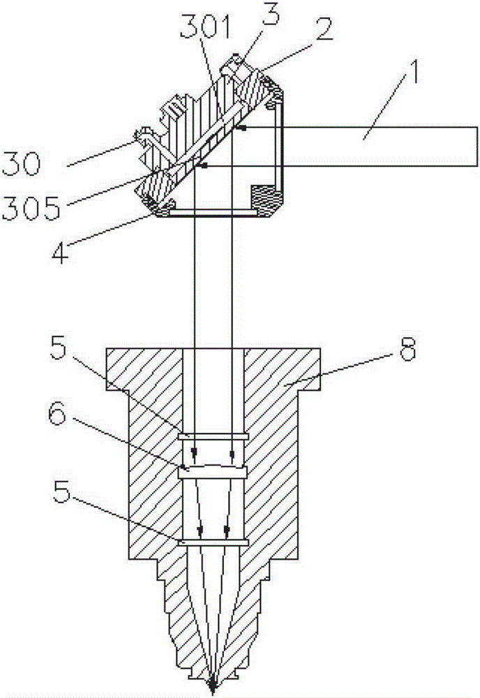
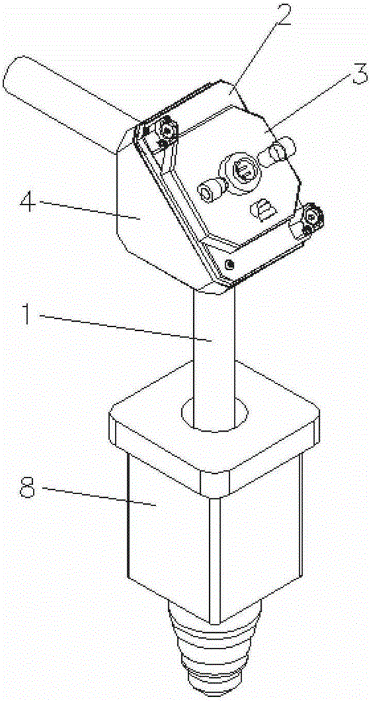
[0016] Embodiment: a pneumatic servo focusing mechanism, comprising a mounting seat 4, a mirror seat 2, a reflector 3 and a laser focusing device, the mounting seat 4 is provided with a light entry channel and a light exit channel, and the mirror seat 2 is embedded in the On the mounting seat 4, the mirror 3 is fixed on the mirror seat 2, a pressure chamber 301 is formed inside the reflector 3, the pressure chamber 301 communicates with the external air source through the pressure interface 30, and the pressure chamber 301 of the reflector 3 faces the interior of the mounting seat 4 One side wall is a lens film 305 whose curvature can be changed under pressure. The lens film 305 can reflect the light beam in the light entrance channel and then enter the beam channel of the laser focusing device through the light exit channel. The laser beam 1 passes through the reflecting mirror 3 After reflection, the lens film 305 enters the laser focusing device to focus on the focus, and th...


PUM


Abstract

The invention discloses a pneumatic servo focusing mechanism, which comprises a mounting seat, a lens seat, a reflecting mirror and a laser focusing device, wherein a light-in passage and a light-out passage are arranged on the mounting seat; the lens seat is embedded into the mounting seat; the reflecting mirror is fixed on the lens mirror; a pressure cavity is formed in the reflecting mirror and is communicated with the outside through a pressure interface; and the side wall, facing towards the inner side of the mounting seat, of the pressure cavity is a lens film the curvature factor of which is changed under action of the pressure; and through the lens film, the light beams in the light-in passage can be reflected to shine into a light beam passage of the laser focusing device through the light-out passage. According to the invention, the quick focusing of the reflecting mirror is realized through changing the curvature factor of the lens film due to pressure, and therefore the focusing mechanism has the advantages of simple structure, convenience in use and low processing and manufacturing expenses.

Description

technical field [0001] The invention relates to a focusing mechanism, in particular to a pneumatic servo focusing mechanism. Background technique [0002] Laser processing equipment uses high-energy laser beams to perform cutting, welding, engraving, heat treatment, etc. on materials or material surfaces. After the laser beam emitted by the laser is transmitted through the optical path, it reaches the focusing mirror to focus the beam, and the energy density at the focus is extremely large. Different processing techniques require different positions of the focal point of the laser beam relative to the material surface, so the laser processing equipment must have the function of adjusting the position of the focal point. [0003] In the current laser processing equipment, there are mainly two ways to adjust the focus position: manual focus adjustment (rotate the distance between the capacitive servo sensor located at the front end of the laser processing head relative to the...

Claims


Application Information

Patent Timeline
Patent Type & Authority Patents(China)
IPC IPC(8): B23K26/046
Inventor 沈晖龚张平施志虎
Owner SUZHOU LEAD LASER TECH
Learn More