
Punching and cutting rivet

A technology of rivets and nail mandrels, which is applied in the direction of rivets, thin-plate connections, and connecting components, can solve problems such as production difficulties, lower production efficiency, and drilling processing difficulties, so as to solve processing difficulties, improve production efficiency, reduce labor intensity and The effect of production costs

Inactive Publication Date: 2013-08-07
刘晓之
View PDF5 Cites 1 Cited by
  • Summary
  • Abstract
  • Description
  • Claims
  • Application Information

AI Technical Summary

Problems solved by technology

[0003]At present, when the workpiece to be riveted is a two-layer or multi-layer metal plate with pre-set holes, and a flexible material pad for sealing is sandwiched between the metal plates, such asFigure 5 shows the following problems during construction: In actual production, the shape and size of the preset holes of two or more layers of metal plates can be controlled, but the sealing strip clamped in the middle is a flexible material that is difficult to shape. Plate pre-hole alignment
Firstly, this construction method adds a process, increases labor costs, and reduces production efficiency; secondly, this production process brings great production difficulties, because the flexible material is elastic, when the drill drills through the flexible material, Then after exiting, the hole will close automatically, so it is very difficult for the rivet without piercing function to pass through the hole again, the production efficiency is very low, and the operator is also time-consuming and laborious.
There is also a process of piercing rivets, with tapered needles on the mandrel or cap head, but in actual use, due to its tapered design, the flexible material stretches to the periphery of the hole and hugs the cone tightly, resulting in huge Friction, construction is more difficult than drilling

Method used


Image

  • Punching and cutting rivet
  • Punching and cutting rivet
  • Punching and cutting rivet

Examples


Embodiment

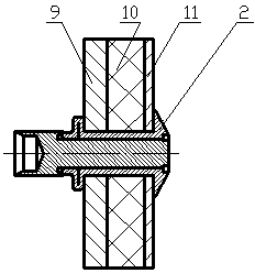
[0022] Such as figure 1 , image 3 , Figure 5 As shown, the reserved hole is processed at the same time after the pressing plate and the riveted workpiece are pressed to ensure the concentricity of the reserved hole, and then a flexible material pad is placed between the pressing plate and the riveted workpiece; body, insert the mandrel rod into the nozzle of the riveting tool, align the head of the mandrel cap with the reserved hole on the pressure plate, and make the piercing cutting edge vertically press the flexible material pad, push forward with force, and the piercing and cutting edge cuts Wear a flexible material pad, and then pull the riveting after the mandrel cap head compacts the riveted workpiece. The mandrel cap head and part of the pipe body pass through the pressing plate, the flexible material pad and the riveted workpiece are locked together. Since there is a countersunk hole in the cap head of the nail core, the end face of the countersunk hole is de...


PUM


Abstract

The invention provides a punching and cutting rivet which is composed of a rivet body and a rivet stem. A cap edge is arranged at one end of the rivet body, a pipe body is arranged at the other end of the rivet body, and a through hole is arranged in a cavity. A rivet stem cap head is arranged at one end of the rivet stem, a rivet stem rod is arranged at the other end of the rivet stem, a counter bore is arranged in the rivet stem cap head, a punching and cutting edge is arranged on the end face of the counter bore, and the rivet stem rod penetrates in the rivet body from one end of the pipe body and is matched with the rivet body mutually. When flexible material pads for sealing and non-metal materials are clamped between or among two-layer or multi-layer metal plates with holes, and the metal plates serve as a riveting workpieces, the punching and cutting rivet reduces original separate machining processes of the flexible material pads and non-metal materials, solves the problem of flexible material pad machining difficulties, enables punching and riveting to be completed once, achieves the purpose of connection and fixation of the workpiece, greatly reduces labor intensity of operators and production cost, and improves production efficiency.

Description

technical field [0001] The invention relates to a piercing rivet, which can be pierced and riveted at one time. It is suitable for sheet metal, cabinets, furniture, doors and windows, air ducts, automobiles, trains, containers, construction and other fields. Background technique [0002] Blind rivets are widely used in occasions that need to be connected and fixed, especially in occasions where double-sided riveting is inconvenient. [0003] At present, when the workpiece to be riveted is two or more layers of metal plates with preset holes, and a flexible material pad for sealing is sandwiched between the metal plates, such as Figure 5 As shown, there are the following problems in the construction process: In actual production, the shape and size of the preset holes of two or more layers of metal plates can be controlled, but the sealing strip clamped in the middle is a flexible material that is difficult to shape. If the riveting hole is set, it is difficult to align t...

Claims


Application Information

Patent Timeline
IPC IPC(8): F16B19/08F16B5/04
Inventor 刘晓之
Owner 刘晓之
Learn More