

Large-scale embedded blanking mould
An insert type, mold technology, applied in the field of blanking molds, can solve the problems of difficult production, sharpening, maintenance, disassembly and assembly, short mold life, etc., and achieve the effect of solving the overall processing difficulties.
- Summary
- Abstract
- Description
- Claims
- Application Information
AI Technical Summary
Problems solved by technology
Method used
Image

Examples
specific Embodiment approach 1
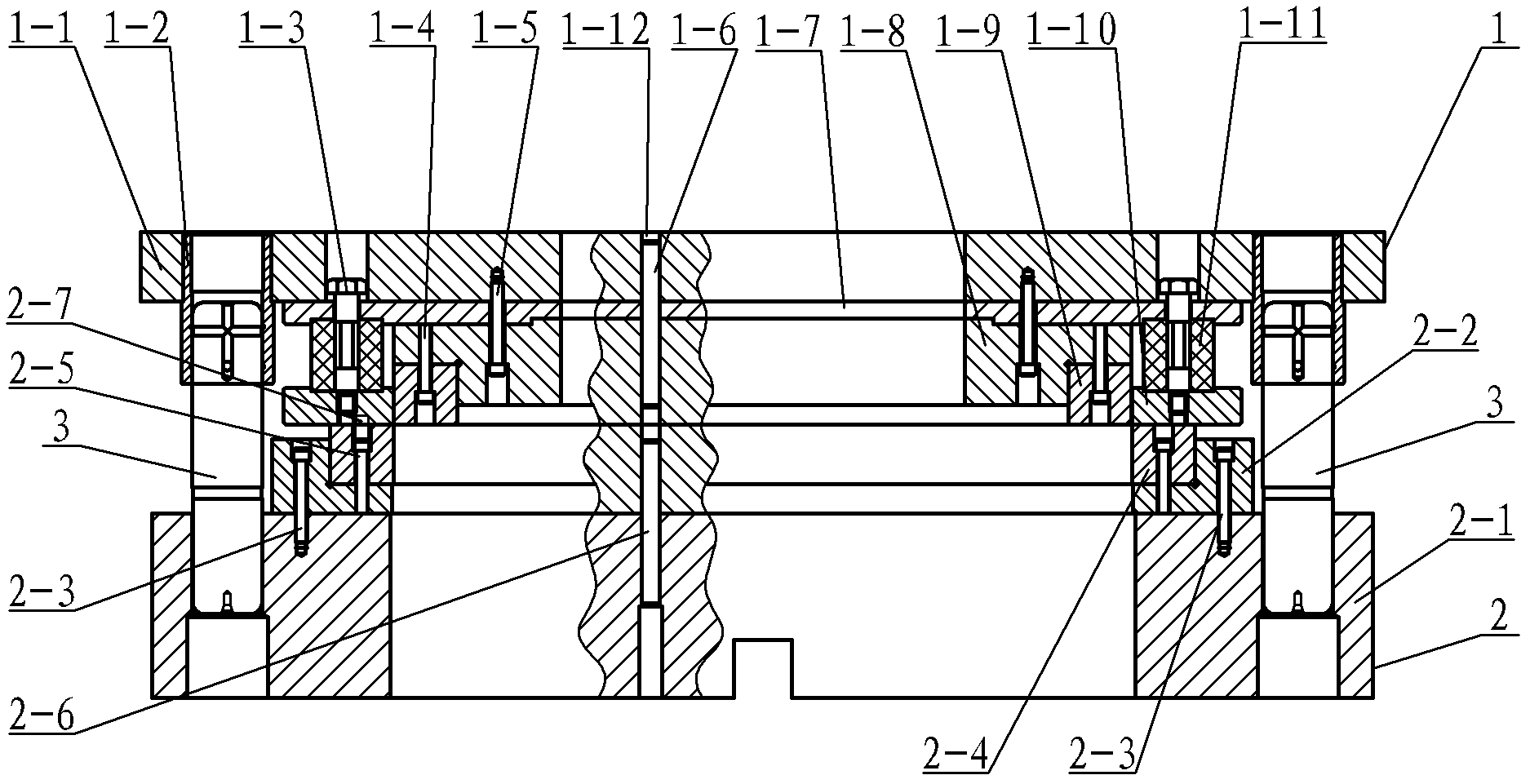
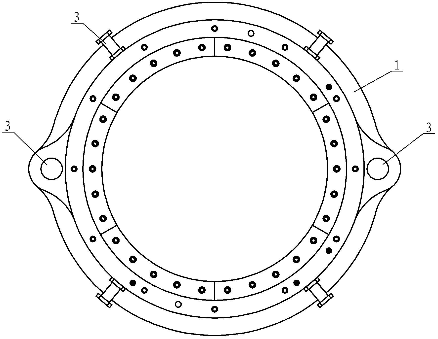
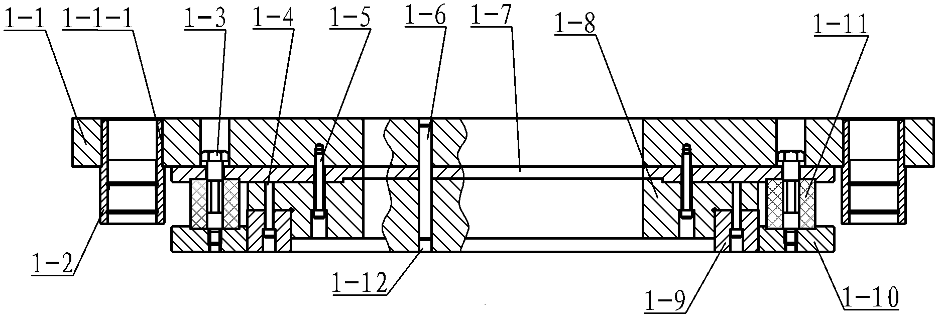
[0009] Specific implementation mode one: combine Figure 1 to Figure 14 Describe this embodiment, this embodiment comprises upper die assembly 1, lower die assembly 2 and at least two guide posts 3, upper die assembly includes upper die base 1-1, punch backing plate 1-7, punch Fixed plate 1-8, unloading ring 1-10, at least two guide sleeves 1-2, two punch positioning pins 1-6, at least four insert punches 1-9, eight unloading rubbers 1- 11 Several discharge screws 1-3, several punch fixing screws 1-4 and several fixing screws 1-5, and at least two guide sleeve holes 1-1- 1. A guide sleeve 1-2 is installed in each guide sleeve hole 1-1-1, and the guide sleeve 1-2 and the upper mold base 1-1 are assembled by interference fit, and at least four insert punches 1-9 The formed ring assembly is arranged on the outer surface of the flange 1-8-1 of the lower end face of the punch fixing plate 1-8, and each insert punch 1-9 is fixed on the punch by the insert punch fixing screw 1-4. O...
specific Embodiment approach 2
[0010] Specific implementation mode two: combination Figure 7 , Figure 8 , Figure 13 and Figure 14 To illustrate this embodiment, each insert punch 1-9 of this embodiment corresponds to the end face of the insert die 2-4 and is provided with an upper die plane or an upper die convex surface along the arc length direction, and each insert die 2-4 The end surface corresponding to the insert punch 1-9 is provided with a lower mold convex surface or a lower mold plane corresponding to the upper mold plane or the upper mold convex surface along the arc length direction, that is, each insert punch 1-9 is connected to the When the end face corresponding to the insert die 2-4 is the plane of the upper die along the arc length direction, the end face corresponding to each insert die 2-4 and the insert punch 1-9 is the lower die convex face along the arc length direction , when the end face of each insert punch 1-9 corresponding to the insert die 2-4 is the convex surface of the ...
specific Embodiment approach 3
[0011] Specific implementation mode three: combination Figure 6 and Figure 12 The present embodiment will be described. The number of insert punches 1-9 and insert dies 2-4 in this embodiment is six. This design makes the lower end face of the ring assembly formed by six insert punches 1-9 and the upper end face of the ring assembly formed by six insert dies 2-4 have many waves along the circumference, and the punching shear area is small and punching The cutting force is small. Other components and connections are the same as those in the first embodiment.
PUM
 Abstract
Description
Claims
Application Information