Uniform lubricating system of high-speed rolling bearings

A lubrication system and high-speed rolling technology, which is applied in the field of bearing lubrication system and uniform lubrication system of high-speed rolling bearings. It can solve problems such as temperature rise, affecting bearing performance, burning, etc., achieve uniform temperature distribution, improve service life and work performance , evenly distributed effect

Inactive Publication Date: 2013-08-07
BEIJING INSTITUTE OF TECHNOLOGYGY
View PDF4 Cites 9 Cited by
  • Summary
  • Abstract
  • Description
  • Claims
  • Application Information

AI Technical Summary

Problems solved by technology

[0003] The rolling elements and cages of the main shaft support bearings of high-speed transmissions also rotate at a relatively high speed. Coupled with the structural limitations in the vehicle gearbox, oil injection lubrication can be used to lubricate the bearings to achieve a good lubrication effect, but oil injection When lubricating, one point is often used for spraying. The lubricating oil sprayed into the bearing is mainly driven by the rotation of the rolling elements and the cage, so that the distribution of the lubricating oil in the bearing along the circumferential direction is uneven, and the oil distribution is uneven. Unevenness leads to uneven convective heat dissipation in the bearing along the circumferential direction, resulting in uneven temperature distribution around the bearing circle, which will lead to excessive local temperature rise of the bearing or even burning, which will affect the performance of the bearing and reduce the bearing performance. The reliability of the bearing shortens the life of the bearing, which in turn affects the reliability and performance of the entire transmission

Method used


Image

  • Uniform lubricating system of high-speed rolling bearings
  • Uniform lubricating system of high-speed rolling bearings
  • Uniform lubricating system of high-speed rolling bearings

Examples


Embodiment Construction

[0017] The specific implementation of the present invention will be further described below in conjunction with the accompanying drawings and examples. The following examples are only used to illustrate the technical solutions of the present invention more clearly, but not to limit the protection scope of the present invention.

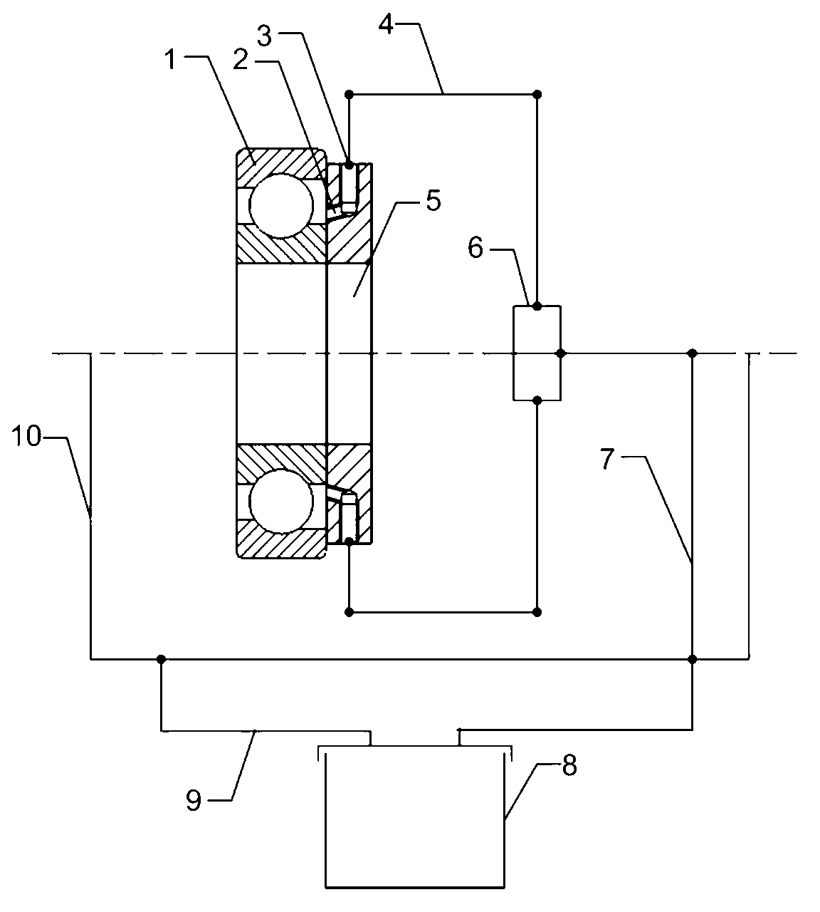
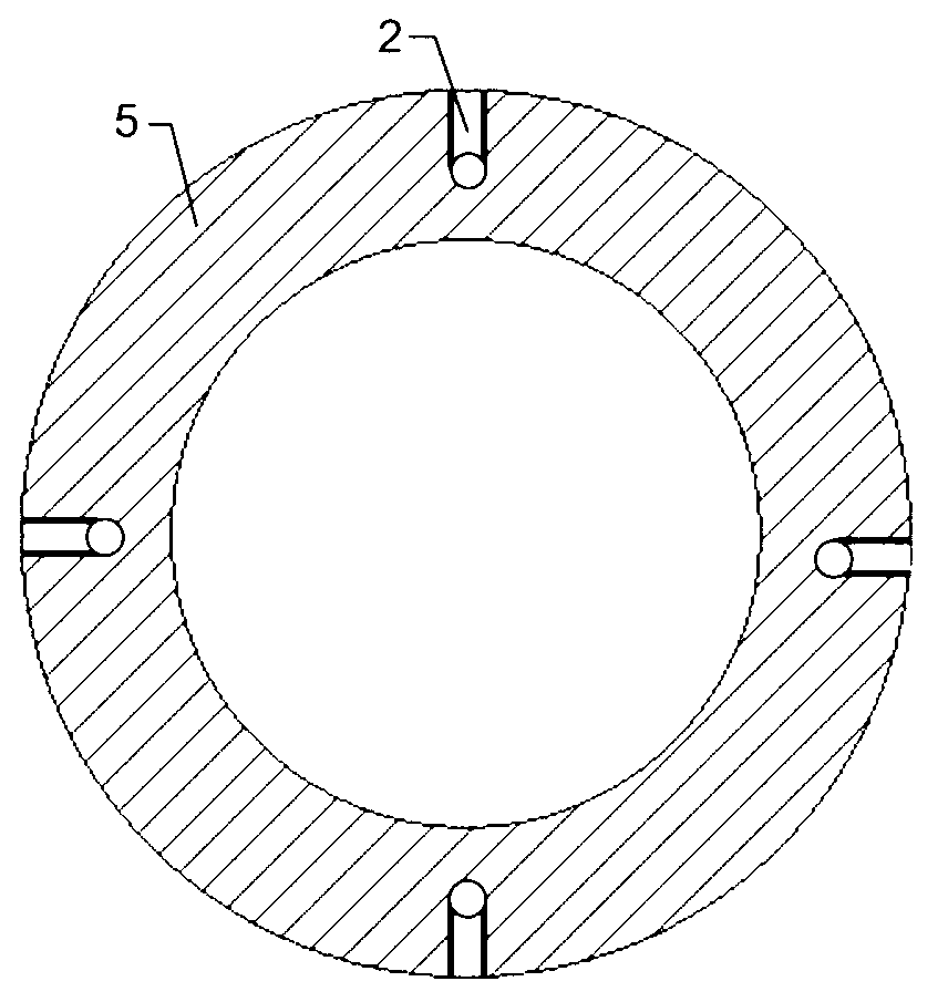
[0018] Such as figure 1 As shown, the technical solution specifically implemented by the present invention is a uniform lubrication system for high-speed rolling bearings, including bearing lubrication oil injection holes 2, lubrication nozzles 3, oil injection hole support plates 5, lubricating oil pipelines 4, and three-way valves 6;

[0019] The lubricating oil from the oil tank 8 reaches the three-way valve 6 after passing through the oil inlet pipeline 7. After passing through the three-way valve 6, the lubricating oil is divided into two paths, and then reaches the lubricating oil nozzle 3 through each oil distribution pipeline 4, and the support...


PUM


Abstract

The invention belongs to the technical field of fluid lubrication and relates to a uniform lubricating system of high-speed rolling bearings. The system specifically comprises bearing lubricating oil jetting holes, two lubricating nozzles, an oil jetting hole support disc, a lubricating oil pipeline and a three-way valve. After coming out of an oil tank, lubricating oil reaches the three-way valve after passing through an oil inlet pipeline, then is divided into two ways after passing through the three-way valve, and finally reaches the lubricating oil nozzles after passing through oil distributing pipelines. A plurality of lubricating oil jetting holes are formed in the support disc at one sides of the bearings. The lubricating oil is jetted to oil jetting points on the bearings after passing through the lubricating oil jetting holes to realize multi-point jet lubrication and further uniform lubrication of the bearings.

Description

technical field [0001] The invention belongs to the technical field of fluid lubrication, and relates to a bearing lubrication system, in particular to a uniform lubrication system for high-speed rolling bearings. Background technique [0002] With the development of modern technology, people have higher and higher requirements for the performance of the transmission device, and the requirements for the DN value of the bearing are also higher and higher. The bearing will generate a lot of heat under the high DN value, so it is necessary to carry out reasonable maintenance on the bearing. Lubrication, the heat of the bearing is taken away by the convection of the oil, thereby improving the working performance and reliability of the bearing. Therefore, research in this area is progressing rapidly. [0003] The rolling elements and cages of the main shaft support bearings of high-speed transmissions also rotate at a relatively high speed. Coupled with the structural limitation...

Claims


Application Information

Patent Timeline
Patent Type & Authority Applications(China)
IPC IPC(8): F16C33/66
Inventor 苑士华吴明星吴维胡纪滨
Owner BEIJING INSTITUTE OF TECHNOLOGYGY
Why Eureka
Try Eureka