
Antenna Test Stand

An antenna test stand and fixed stand technology, applied in the directions of measuring devices, measuring instrument components, instruments, etc., can solve the problems of low test efficiency and difficulty in building a test platform, and achieve the effects of improving test efficiency, occupying less space, and being convenient to carry.

Active Publication Date: 2016-02-17
HUNAN AEROSPACE HUNAYU COMM TECH CO LTD
View PDF5 Cites 0 Cited by
  • Summary
  • Abstract
  • Description
  • Claims
  • Application Information

AI Technical Summary

Problems solved by technology

[0004] The purpose of the present invention is to provide a portable antenna test stand to solve the technical problems of difficulty in building test platforms and low test efficiency

Method used


Image

  • Antenna Test Stand
  • Antenna Test Stand
  • Antenna Test Stand

Examples


Embodiment Construction

[0025] The embodiments of the present invention will be described in detail below with reference to the accompanying drawings, but the present invention can be implemented in many different ways defined and covered by the claims.

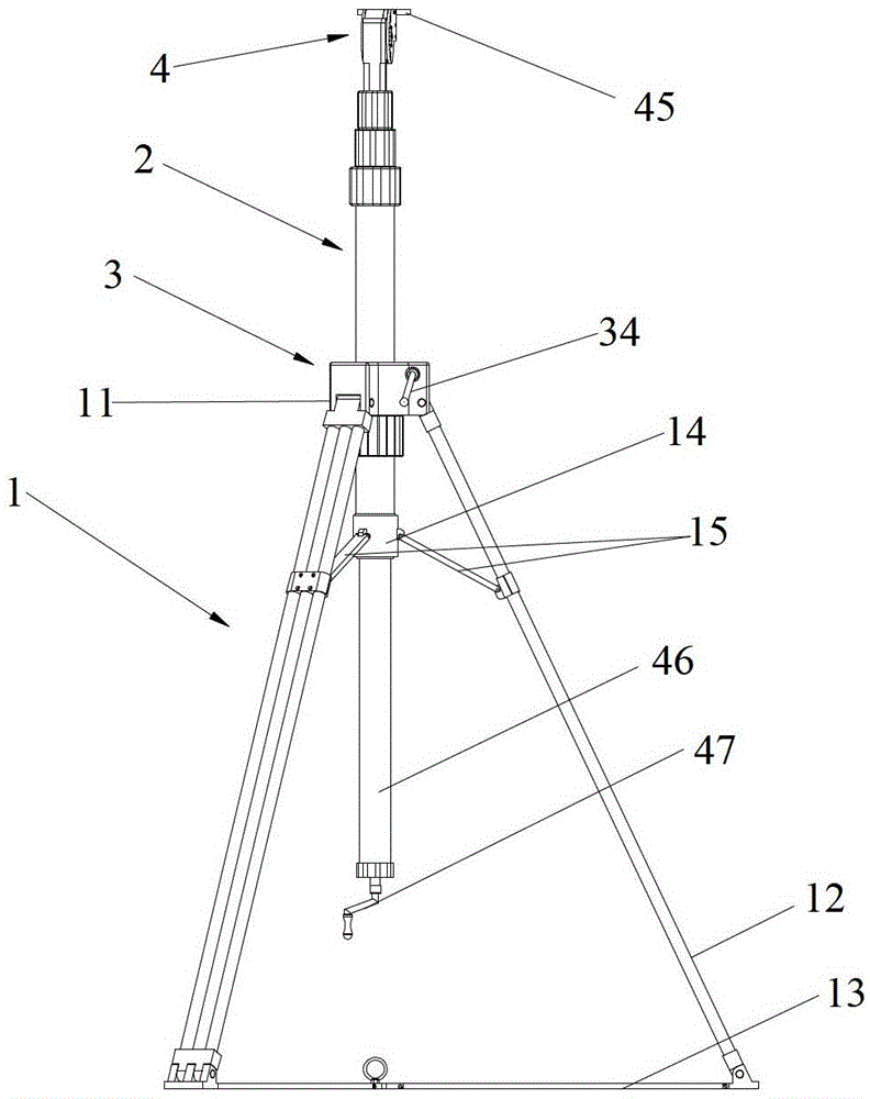
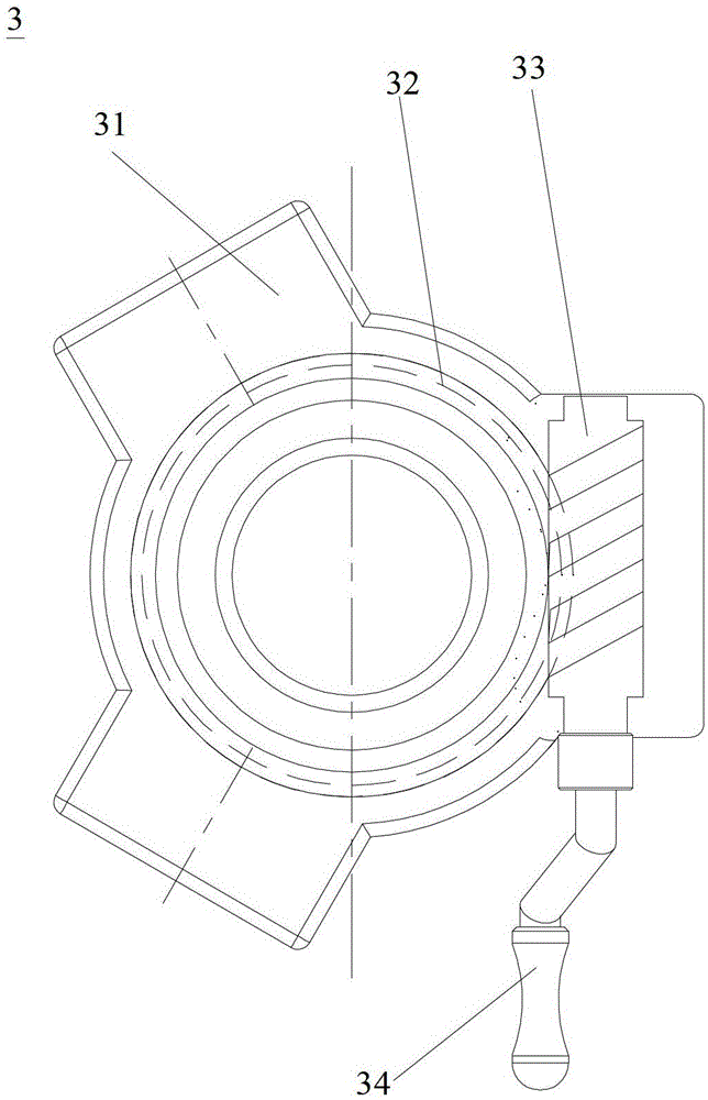
[0026] refer to figure 1 , the preferred embodiment of the present invention provides a kind of antenna testing stand, comprises support mechanism 1, is connected with the height adjustment mechanism 2 that length can be stretched through azimuth adjustment mechanism 3 on support mechanism 1, height adjustment mechanism 2 is in the azimuth adjustment mechanism 3 The azimuth can be adjusted in the horizontal direction under the action. The height adjustment mechanism 2 is provided with a pitch adjustment mechanism 4 for pitch angle adjustment. The support mechanism 1 and the height adjustment mechanism 2 adopt a folding structure.

[0027] Specifically, in a preferred embodiment, the height adjustment mechanism 2 includes hollow multi-level connectin...


PUM


Abstract

The invention discloses an antenna testing frame, which comprises a support mechanism, wherein a height adjusting mechanism with an adjustable length is connected to the support mechanism through a direction adjusting mechanism; under the action of the direction adjusting mechanism, the height adjusting mechanism can undergo direction adjustment in a horizontal direction; the height adjusting mechanism is provided with a pitching adjusting mechanism for adjusting a pitch angle; and folding structures are adopted by the support mechanism and the height adjusting mechanism. The antenna testing frame can be used for adjusting the direction, pitching and height of an antenna to be tested conveniently to meet the requirement of an antenna performance test; moreover, the folding structures are adopted by the support mechanism and the height adjusting mechanism of the antenna testing frame, so that the antenna testing frame has the advantages of small size, small space occupation and convenience in carrying after being folded; and the antenna testing frame can be applied to indoor and outdoor antenna tests conveniently, the problem of difficulty in erecting a testing platform is solved, and the testing efficiency is increased.

Description

technical field [0001] The invention relates to the field of antenna testing, in particular to an antenna testing frame. Background technique [0002] The test of antenna performance involves multiple indicators, and needs to be tested for multiple items indoors and outdoors. The indoor test platform is generally built in the microwave dark room, the position is fixed and cannot be moved at will; the outdoor test platform is generally built on the roof of a high-rise building or in a dedicated test field. Some small antennas need to test antenna indicators in different environments, such as: cities, mountains, river valleys, cultivated land, islands and other places. When it is necessary to conduct antenna tests in these different locations, it is necessary to build a test platform in the corresponding location. Doing so not only wastes resources but also affects the progress of antenna testing. [0003] Therefore, there is an urgent need to design an antenna test stand th...

Claims


Application Information

Patent Timeline
Patent Type & Authority Patents(China)
IPC IPC(8): G01D11/30
Inventor 彭国勋李完小李治斌马花莉
Owner HUNAN AEROSPACE HUNAYU COMM TECH CO LTD
Learn More