
Intelligent hydraulic machine stroke limiting device

A stroke limit and hydraulic press technology, which is applied in the field of intelligent hydraulic press stroke limit devices, can solve problems such as affecting the use of equipment, and achieve the effect of convenient use and convenient orientation adjustment processing.

Active Publication Date: 2021-04-16
滕州市百兴机械有限公司
View PDF6 Cites 0 Cited by
  • Summary
  • Abstract
  • Description
  • Claims
  • Application Information

AI Technical Summary

Problems solved by technology

[0004] The current stroke limit devices of hydraulic presses are generally installed with limit rods at the four corners outside the hydraulic cylinder and hydraulic rod, so as to realize the smooth movement of the hydraulic cylinder, but the corresponding hydraulic cylinder can only be fixed with a specific stroke limit device, so that Affect the use of equipment

Method used


Image

  • Intelligent hydraulic machine stroke limiting device
  • Intelligent hydraulic machine stroke limiting device
  • Intelligent hydraulic machine stroke limiting device

Examples


Embodiment 1

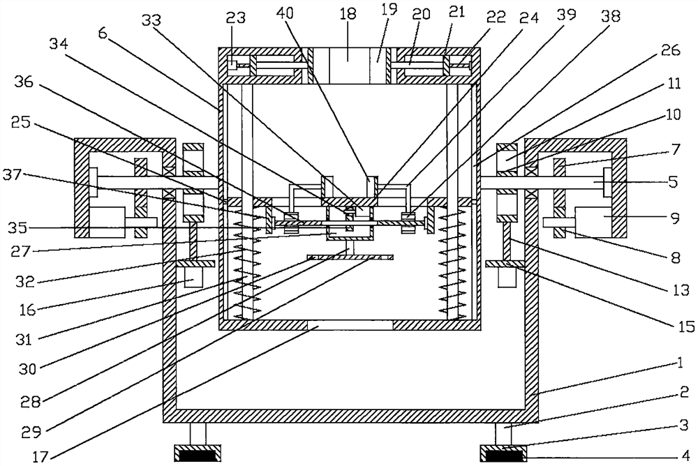
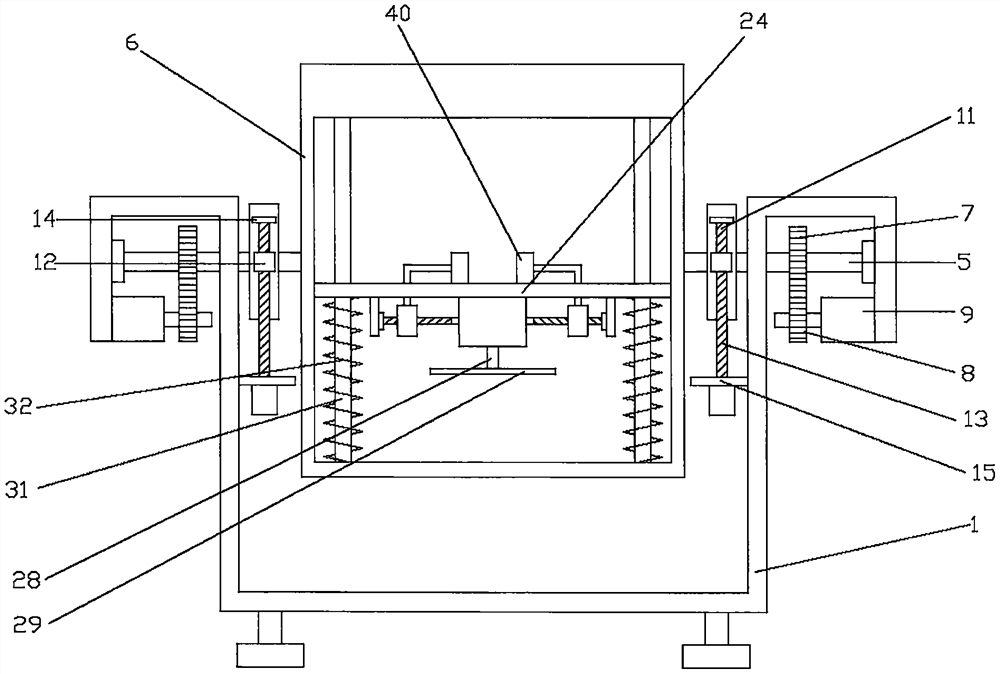
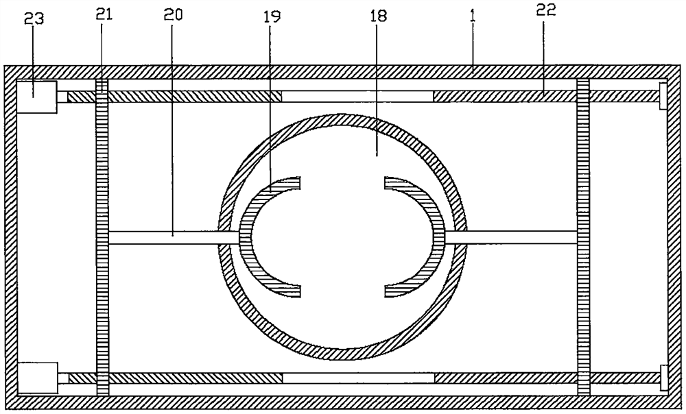
[0027] refer to Figure 1~4 , in an embodiment of the present invention, an intelligent hydraulic machine stroke limit device includes a support frame 1, and the four corners of the lower side of the support frame 1 are fixedly installed with support columns 2, and the lower side of the support column 2 is fixedly installed with support blocks 3, and the support blocks 3 The lower end is inlaid with a friction pad 4, which can effectively increase the friction between the equipment and the ground, so as to ensure the stability of the equipment. The upper end of the support frame 1 is connected with the rotating shaft 5 by connecting the bearing and the bearing seat, which can facilitate the rotation of the rotating shaft 5. The outer end of the rotating shaft 5 is provided with a first gear 7, the lower side of the first gear 7 is meshed with a second gear 8, the outer end of the second gear 8 is equipped with a first motor 9, and the first motor 9 is fixedly installed on the s...

Embodiment 2

[0032] The difference from Embodiment 1 is that a friction pad 10 is provided on the rotating shaft 5 inside the support frame 1, a brake block 11 is provided outside the friction pad 10, and first sliders 12 are fixedly installed on the front and rear sides of the brake block 11. The first slider 12, the first slider 12 is internally threaded with a one-way threaded rod 13, the upper side of the one-way threaded rod 13 is fixedly installed with a limit block 14, and the lower side of the one-way threaded rod 13 is provided with a mounting block 15, the mounting block 15 is connected with the support frame 1, a second motor 16 is installed on the lower side of the mounting block 15, and the upper side of the second motor 16 is connected with the one-way threaded rod 13, and the one-way threaded rod 13 is driven to rotate by the single machine 16, The one-way threaded rod 13 drives the brake block 11 to move upwards, so that the brake block 11 can be closely connected with the f...


PUM


Abstract

The invention relates to the field of hydraulic pressure, in particular to an intelligent hydraulic machine stroke limiting device. The intelligent hydraulic machine stroke limiting device comprises a supporting frame, wherein the upper end of the supporting frame is provided with a rotating shaft; the outer end of the rotating shaft is provided with a first gear, the lower side of the first gear is meshed with a second gear, and the outer end of the second gear is provided with a first motor; the inner side of the rotating shaft is provided with a connecting frame, the top of the connecting frame is provided with a second opening, and first clamping plates are arranged at the two ends of the second opening; first connecting plates are arranged on the outer sides of the first clamping plates through connecting rods, and first one-way threaded rods are arranged at the front ends and the rear ends of the first connecting plates; limiting rods are arranged inside the connecting frame, second connecting plates are arranged on the limiting rods, and sealing covers are arranged on the lower sides of the second connecting plates; and second two-way threaded rods are arranged on the sealing covers, second sliding blocks are in threaded connection with the second two-way threaded rods, and the upper sides of the second sliding blocks are connected with second clamping plates through connecting pieces. According to the intelligent hydraulic machine stroke limiting device, hydraulic devices with different specifications can be effectively and conveniently clamped, and therefore equipment can be conveniently used.

Description

technical field [0001] The invention relates to the hydraulic field, in particular to an intelligent hydraulic press stroke limiting device. Background technique [0002] A hydraulic press (also known as: hydraulic press) is a machine that utilizes hydrostatic pressure, uses liquid as the working medium, and uses Pascal's principle to transfer energy to process metal, plastic, rubber, wood, powder and other products. [0003] A hydraulic press generally consists of three parts: the machine (main machine), the power system and the hydraulic control system. Hydraulic presses are classified into valve hydraulic presses, liquid hydraulic presses, and engineering hydraulic presses. [0004] The current stroke limit devices of hydraulic presses are generally installed with limit rods at the four corners outside the hydraulic cylinder and hydraulic rod, so as to realize the smooth movement of the hydraulic cylinder, but the corresponding hydraulic cylinder can only be fixed with a...

Claims


Application Information

Patent Timeline
Patent Type & Authority Applications(China)
IPC IPC(8): B30B15/00
Inventor 王兆明王兆星王维旭
Owner 滕州市百兴机械有限公司
Learn More