Krischner wire with sliding sleeve

A K-wire and sliding sleeve technology, applied in the field of K-wires, can solve the problems of incompatibility, reduction, and inconvenience in use.

Inactive Publication Date: 2013-08-14
史艳光
View PDF0 Cites 4 Cited by
  • Summary
  • Abstract
  • Description
  • Claims
  • Application Information

AI Technical Summary

Problems solved by technology

[0002]At present, orthopedic surgeons often use Kirschner wire to treat patella, olecranon, greater trochanter of femur and other bone end avulsion fractures. It is easy to operate, economical and practical. However, problems such as Kirschner wire sliding and wandering during use, inconvenient bending, steel wire not being close to the bone end and slipping, Kirschner wire not matching the steel wire, and inability to move early after surgery may occur, which bring a lot of trouble to both doctors and patients, resulting in Unnecessary disputes, so the use of ordinary Kirschner wires gradually decreased
People have carried out a lot of improvements to it, and multiple holed Kirschner wires have occurred, but many holes are drilled on the Kirschner wire body, such as "Band Hole Kirschner wires" announced on August 25, 1999 (patent No. 2334356Y ), on the one hand, the strength of the Kirschner wire is reduced; on the other hand, the tension band material cannot be penetrated in advance for fracture fixation drilling, which is very inconvenient to use

Method used


Image

  • Krischner wire with sliding sleeve
  • Krischner wire with sliding sleeve
  • Krischner wire with sliding sleeve

Examples


Embodiment Construction

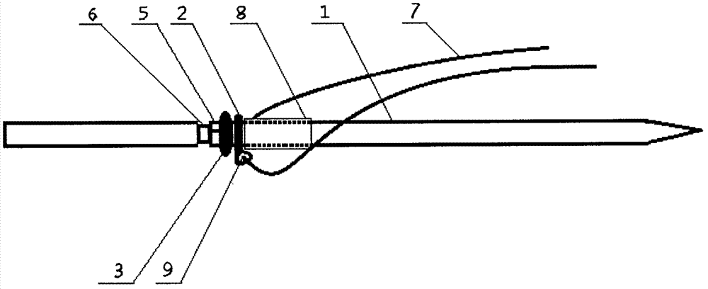
[0008] The present invention will be described in detail below in conjunction with the accompanying drawings.

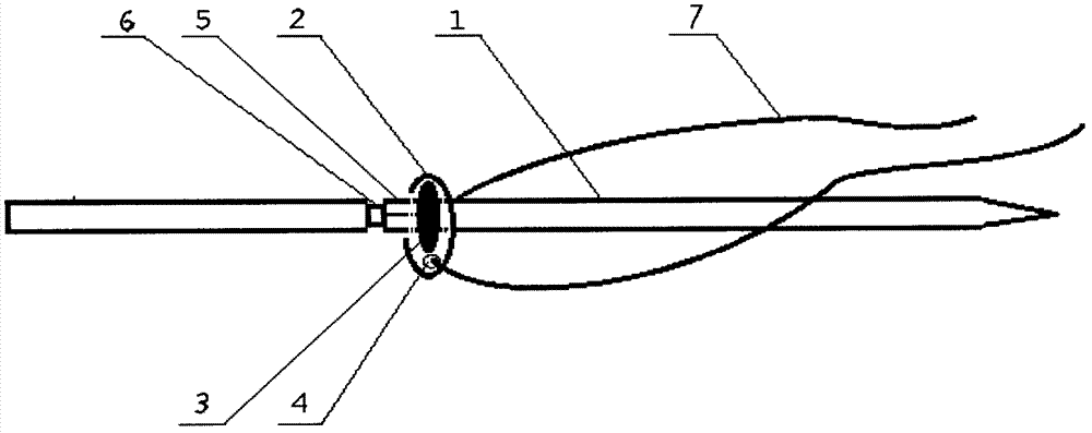
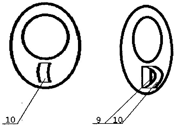
[0009] as attached figure 2 As shown, there is a boss (3) on the needle tail side of the needle body section of the Kirschner wire (1), and a small section of thread (8) protruding from the surface of the Kirschner wire on the needle tip side, between the boss (3) and the thread There is a sliding sleeve (2) between the (8), and the sliding sleeve (2) can freely rotate along the longitudinal axis of the needle body, but the sliding sleeve (2) is restricted by the boss (3) and the thread (8), and cannot rotate along the needle body. The longitudinal axis of the body moves up and down obviously, and an ear handle (10) with a hole (9) protrudes from the side of the sliding sleeve, so that the tension band material (7) can pass through the hole (9), and the end of the Kirschner wire The caudal half of the side boss (3) is a section of polyhedron (5), which is convenien...


PUM


Abstract

The invention provides a krischner wire with a sliding sleeve, is used for multiple-fracture treatment, and belongs to orthopedics instruments. The sliding sleeve (2) is sleeved in a wire body section of the krischner wire (1), the wire body section of the krischner wire is provided with one or two bosses (3), the sliding sleeve can freely rotate along a vertical axis in the wire body and is limited by the bosses to be not capable of moving up and down obviously along the vertical axis of the wire body, a hole (4) is arranged on or an ear-shaped handle (10) with holes is protruded a side of the sliding sleeve , tension band materials (7) are facilitated to attach to the sliding sleeve. An annular pre-breaking incisura (6) is arranged at a junction between a wire tail end of the krischner wire and the bosses (3) on wire tail side to facilitate to break the wire tail end. The krischner wire and the tension band materials are integrated linked through the sliding sleeve to limit the krischner wire to move in bones, so that the operation is facilitated, and fixing is reliable; and the krischner wire, the sliding sleeve and the tension band materials can be made of metal or high molecular materials, and can be sterilized in an integral package.

Description

technical field [0001] The invention belongs to an orthopedic medical instrument, in particular to a Kirschner wire with a sliding sleeve which can be used for the treatment of multiple fractures. technical background [0002] At present, orthopedic surgeons often use Kirschner wires to treat patella, olecranon, greater trochanter and other bone end avulsion fractures. It is easy to operate, economical and practical, but the Kirschner wires will slide, wander and be inconvenient to bend during use. , The steel wire is not close to the bone end and slips, the Kirschner wire is not compatible with the steel wire, and the problems such as inability to move early after the operation have brought a lot of troubles to both doctors and patients, causing unnecessary disputes, so the use of ordinary Kirschner wires has gradually decreased. People have carried out a lot of improvements to it, and multiple holed Kirschner wires have occurred, but many holes are drilled on the Kirschner...

Claims


Application Information

Patent Timeline
Patent Type & Authority Applications(China)
IPC IPC(8): A61B17/68
CPCA61B17/683
Inventor 史艳光
Owner 史艳光
Why Eureka
Try Eureka