High-speed reeling machine

A high-speed coil and reel technology, applied in the field of rolling mill supporting equipment, can solve the problems of difficult alignment of edges, low winding precision, and uneven layers at both ends of the strip coil, so as to reduce the number of roll changes, high winding precision, The effect of large winding diameter

Inactive Publication Date: 2013-08-14
无锡亚新通用机械有限公司
View PDF7 Cites 5 Cited by
  • Summary
  • Abstract
  • Description
  • Claims
  • Application Information

AI Technical Summary

Problems solved by technology

In addition, due to the difficulty in aligning the edges during the winding process of the steel strip, the layers at both ends of the rolled strip are uneven, and the winding accuracy is low.

Method used


Image

  • High-speed reeling machine
  • High-speed reeling machine

Examples


Embodiment Construction

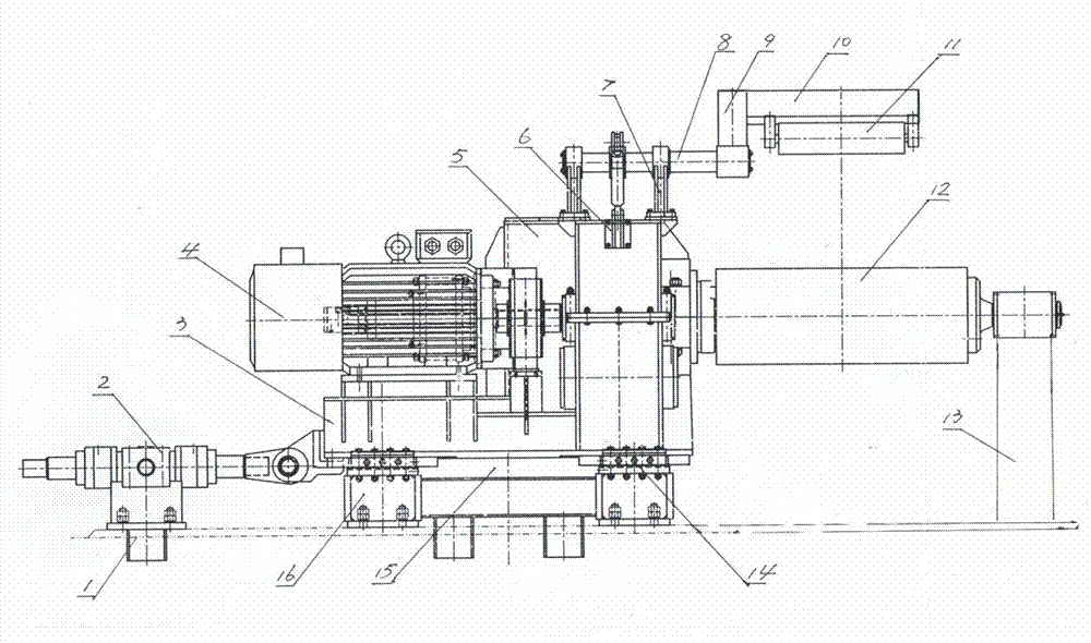
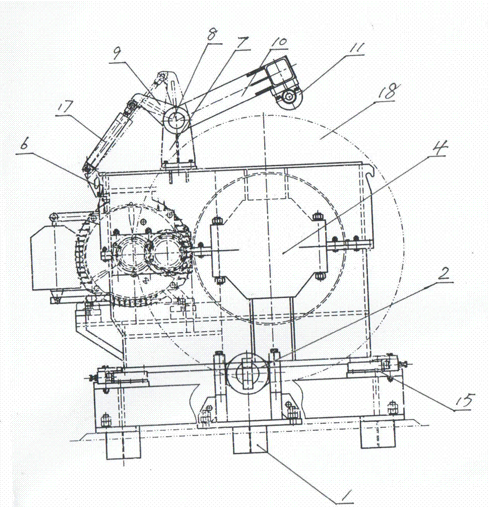
[0012] Such as figure 1 and figure 2 As shown, the high-speed coiler of the present invention includes a base 16, the base 16 is rectangular, two guide rails 15 are arranged on the top of the base 16, and the two guide rails 15 are parallel and arranged along the longitudinal sides of the base 16. A frame 3 is arranged on the base 16, and the frame is rectangular. The bottom of the frame 3 is equipped with two rows of rollers 14 by means of a wheel seat and a wheel shaft, and the two rows of rollers 14 are respectively placed in the corresponding tracks 15 on the top of the base 16 and can roll along the longitudinal direction of the tracks 15 . The frame 3 is provided with a motor 4, a reduction box 5 and a reel 12, the output shaft of the motor 4 is connected with the input shaft of the reduction case 5, and the output shaft of the reduction case 5 is connected with one end of the reel 12. A first support 13 is provided below the outer end of the reel 12 , and the end of ...


PUM


Abstract

The invention relates to a high-speed reeling machine, and particularly relates to a high-speed reeling machine for reeling steel belts rolled by a rolling mill. The high-speed reeling machine comprises a base which is provided with a stander; the stander is provided with an electric motor, a speed reducer and a reel; an output shaft of the electric motor is fixedly connected with an input shaft of the speed reducer and an output shaft of the speed reducer is fixedly connected with the reel; the outer end of the reel is arranged on a first bracket by means of a shaft; and a winding drum is sleeved on the reel in a reeling state. The high-speed reeling machine is characterized in that the base is provided with two rails parallel to each other; and two columns of rollers are arranged at the bottom of the stander, are respectively arranged in the corresponding rails and can roll along the longitudinal direction of the rails. A second bracket is arranged on one side, far away from and opposite to the reel, of the base, a first hydraulic oil cylinder is fixed on the second bracket, and a piston rod of the first hydraulic oil cylinder is hinged with the stander together. The high-speed reeling machine is used for reeling steel belts, and is large in reeling diameter and high in reeling precision.

Description

technical field [0001] The invention relates to a rolling mill matching equipment. Specifically, it is a high-speed coiler used to coil the steel strip rolled out of the rolling mill. Background technique [0002] At present, in the strip rolling industry, the coilers used to coil the steel strip rolled by the rolling mill are traditional coilers. This traditional coiler includes a base on which a frame is fixed. A motor, a reduction box and a reel are fixed, the output shaft of the motor and the input shaft of the reduction case, the output shaft of the reduction case and the reel are all fixedly connected, and the outer end of the reel is placed on the first bracket by means of a shaft. In the coiled state, the reel is sleeved on the reel. Because the frame of this coiler is fixed with the base, correspondingly, the frame is also positioned in one position, and the reel cannot be adjusted back and forth, which makes it difficult to align the edges during the coiling proc...

Claims


Application Information

Patent Timeline
Patent Type & Authority Applications(China)
IPC IPC(8): B21C47/10
Inventor 孙大南
Owner 无锡亚新通用机械有限公司
Why Eureka
Try Eureka