Valve timing changing device

A timing changing device and air distribution technology, which is applied to valve devices, engine components, machines/engines, etc., can solve problems such as increased size of shell rotor and blade rotor, knocking sound and poor movement, and wear of locking pins , to achieve the effect of miniaturization of the device, prevention of knocking noise and wear, and stable starting performance

Active Publication Date: 2013-08-14
MIKUNI CORP
View PDF5 Cites 0 Cited by
  • Summary
  • Abstract
  • Description
  • Claims
  • Application Information

AI Technical Summary

Problems solved by technology

[0003] In this device, since the lock pin of the lock mechanism reciprocates in a direction parallel to the rotation axis of the camshaft, it is necessary to provide a space portion (restricting groove and escape hole) for the lock mechanism (lock pin) to move relative to the The vane rotor or the housing rotor is accommodated in such a way that it can be moved in and out freely, therefore, in the axial direction of the camshaft, the size of the housing rotor and the vane rotor is increased, and since the hydraulic pressure applied to the advanced angle chamber or the retarded angle chamber is used to perform The unlocking action of the lock is achieved by means of the locking pin, so whenever the advanced angle mode or the retarded angle mode is selected by the control valve, the locking pin will perform the locking or locking unlocking action, that is, frequently repeating the reciprocating movement, which may cause the lock pin There are problems in reliability due to wear, knocking sound, and poor operation (sticking, adhesion, etc.)

Method used


Image

  • Valve timing changing device
  • Valve timing changing device
  • Valve timing changing device

Examples


Embodiment Construction

[0108] Hereinafter, embodiments of the present invention will be described with reference to the drawings.

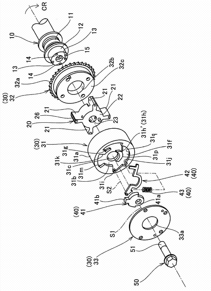
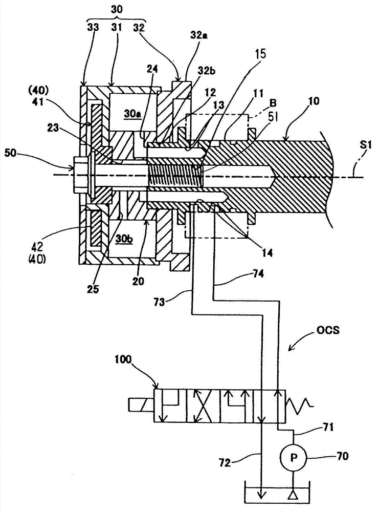
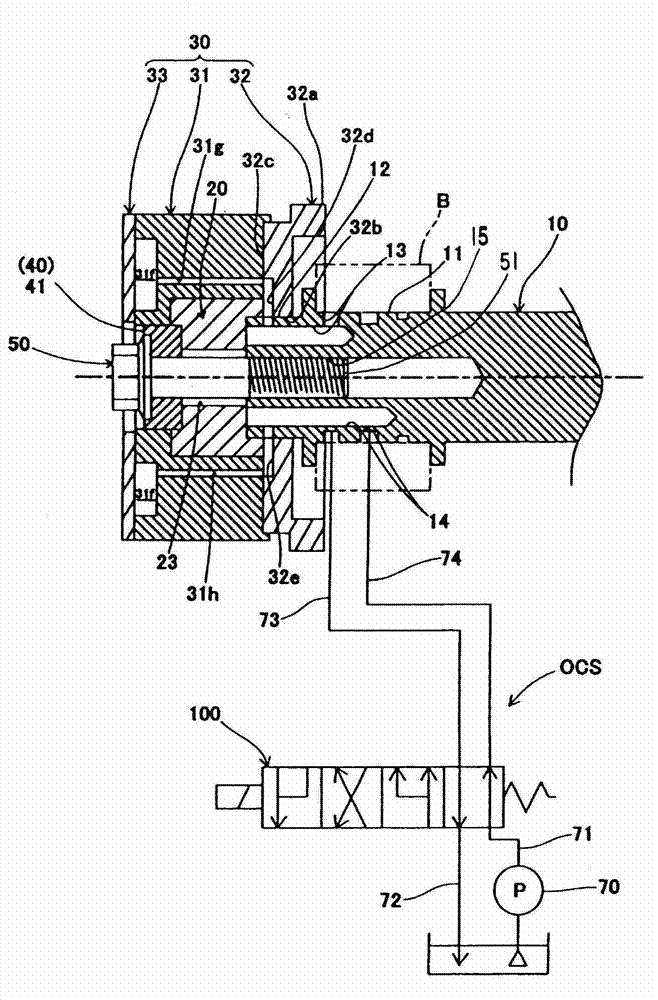
[0109] The valve timing changing device is a hydraulic valve timing changing device that uses the hydraulic pressure of the working oil in the engine to change the valve timing, such as Figure 1 to Figure 3 As shown, it includes the following components, etc.: a vane rotor 20 that is detachably fixed to the camshaft 10; a housing rotor 30 that rotates on the rotation axis S1 of the camshaft 10 and accommodates the vane rotor 20 as Can be rotated relatively, and the casing rotor 30 cooperates with the vane rotor 20 to define an advanced angle chamber 30a and a retarded angle chamber 30b; the locking mechanism 40 (locking cam 41, locking lever 42, force application member 43), its configuration The isolation chamber of the housing rotor 30 to lock the vane rotor 20 in the middle position relative to the housing rotor 30; the central bolt 50, which fastens the vane rotor ...


PUM


Abstract

The invention provides a valve timing changing device, which eliminates unnecessary actions except locking by a locking mechanism used for maintaining a camshaft at a medium position within a predetermined angle range with respect to a shell rotor. The valve timing changing device comprises a shell rotor (30) and a locking mechanism (40); the locking mechanism (40) locks a blade rotor, which is fixed at a camshaft, at a medium position with respect to the shell rotor; the locking mechanism comprises a locking cam (41) which rotates integrally with the camshaft, a locking rod (42) which is supported by the shell rotor and engaged with the locking cam so as to restrict the rotation of the cam from the medium position to an advance-angle side and a lag-angle side, and is detached from the locking cam for unlocking under the action of predetermined unlocking force after engine start, and a force-applying part (43) which generats acting force for engaging the locking rod with the locking cam for locking in a state that the unlocking force is not applied. Therefore, redundant action of the locking rod is eliminated.

Description

technical field [0001] The present invention relates to a valve timing changing device for changing the opening and closing timing (distribution timing) of an intake valve or an exhaust valve of an internal combustion engine according to operating conditions. Background technique [0002] It is known that a conventional valve timing changing device includes the following components, etc.: a housing rotor (outer rotor, rear plate, front plate) that rotates synchronously with the crankshaft; a vane rotor (inner rotor) that rotates synchronously with the camshaft and that Stored in the casing rotor, the storage chamber of the vane rotor is divided into two parts, the retarded angle chamber and the advanced angle chamber, and the vane rotor can rotate relative to the casing rotor by a predetermined action angle (the most advanced angle position and most retarded angular position); locking mechanism (two locking pins and two springs) that locks the vane rotor relative to the hous...

Claims


Application Information

Patent Timeline
IPC IPC(8): F01L1/344
Inventor 福岛义友关谷满连哲朗
Owner MIKUNI CORP
Why Eureka
Try Eureka