Brake clearance manual adjusting arm device with umbrella tooth structures arranged at two ends of worm

A manual adjustment and brake clearance technology, applied in the direction of slack adjuster, etc., can solve the problems of damage to the adjustment shaft locking device, brake failure, and increase of brake clearance

Active Publication Date: 2013-08-14
绍兴铁安汽配制造有限公司
6 Cites 0 Cited by

AI-Extracted Technical Summary

Problems solved by technology

However, the existing adjusting arm generally adopts the self-locking of the adjusting shaft, and its service life is very short. The internal worm gear, worm and locking device mechanisms often fail to self-lock, resulting in the inability of the worm gear and the brake adjusting arm housing to move synchronously. When the vehicle is braking, it will not stop in time after deceleration, and it will not be able to fully return to its position at the end of braking. This will cause hidden dangers in driving. Therefore, this part must be replaced frequently, resulting in unnecessary waste
The self-locking failure is mainly caused by the following factors: In the existing automobile brake system, the automobile brake adjustment arm is mainly composed of the adjustment arm housing, the turbine, the worm and other components. The diameter of the circle and the pressure angle of the helix are the same. During the process of overlapping the transmission torque of the two, due to the fr...

Abstract

The invention discloses a brake clearance manual adjusting arm device with umbrella tooth structures arranged at two ends of a worm. Elastic material working holes with angles are arranged on two fitting surfaces of the worm as well as the front end and the back end of an adjusting arm shell; the umbrella tooth structures at two ends of the worm fit with the elastic material working holes; self-locking is performed on the umbrella tooth structures of the worm by the elastic material at two ends of the shell; and since rigid hardness of the worm is higher than hardness of the adjusting arm shell, for a rack of the umbrella tooth structures on the worm and fitting surfaces of the adjusting arm shell, in an impact process of braking force and reverse braking force, the fitting surfaces of the adjusting arm shell is impacted by the toothed rack of the umbrella tooth structures on the worm to form a gear groove symmetrical with the toothed rack of the umbrella tooth structures. The brake clearance manual adjusting arm device has the advantages of long service life, quick braking, rapid return and convenience in adjustment; assembly is free of restraint on a braking force direction; synchronous motion of the adjusting arm shell and a turbine is implemented; frequent changing is avoided; and sensitivity, reliability and safety of a brake system are further improved.

Application Domain

Slack adjusters

Technology Topic

Brake forceSelf locking +5

Image

  • Brake clearance manual adjusting arm device with umbrella tooth structures arranged at two ends of worm
  • Brake clearance manual adjusting arm device with umbrella tooth structures arranged at two ends of worm
  • Brake clearance manual adjusting arm device with umbrella tooth structures arranged at two ends of worm

Examples

  • Experimental program(1)

Example Embodiment

[0014] Specific implementation plan
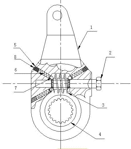
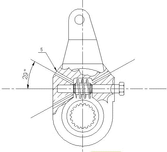
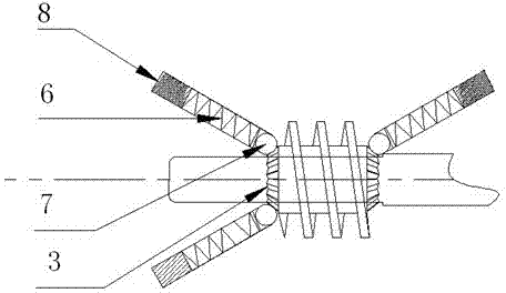
[0015] Such as figure 1 , figure 2 As shown, a brake gap manual adjustment arm device with an umbrella tooth structure at both ends of a worm. The worm lock adjustment arm with rack of the present invention mainly includes an adjustment arm housing (1), an adjustment shaft (2), and a worm ( 3), the turbine (4) and other components, because the two mating surfaces of the adjusting arm housing (1) and the worm (3) are provided with an angled elastic material working hole (5), and the two ends of the worm (3) The umbrella tooth structure and the steel ball (7) in the elastic material working hole (5) coincide with each other.
[0016] When adjusting the brake clearance of the vehicle, the worm shaft (2) rotates, and the bevel gear racks at both ends of the worm (3) rotate at the same time to overcome the pressure generated by the steel ball (7) in the working hole (5), and the steel ball (7) Move from the bottom of the bevel gear rack to the top of the tooth, and after passing the top of the tooth, it will return to the bottom of the tooth under the pressure of the return spring (6) in the working hole (5). When the car is braking, the adjusting arm housing (1) is forced to push the worm (3), and the worm (3) transmits force to the turbine (4), because the adjusting arm housing (1) and the worm (3) coincide The surface is provided with steel balls (7) and the bevel gear racks at both ends of the worm (3) are locked to each other. When braking, because the rigidity of the worm (3) is greater than that of the adjusting arm housing (1), the worm ( 3) The anastomosis surface between the rack of the umbrella tooth structure and the adjusting arm housing (1). During the impact of the braking force and counter-braking force, the umbrella tooth rack on the worm (3) will adjust the arm housing (1) ) The anastomosis plane, impacts into a tooth groove symmetrical to the bevel gear rack, which strengthens the strength of self-locking. The stronger the braking force, the greater the locking and anastomotic force. The braking force generated by the worm (3) and the reverse thrust of the turbine (4) can no longer cause the adjustment shaft (2) to reverse rotation. This brake adjustment arm avoids the increase in the braking gap caused by the adjustment shaft (2) reverse rotation. The phenomenon of brake failure has the advantages of long service life, rapid braking, quick return, convenient adjustment, installation is not restricted by the direction of braking force, and synchronization of the adjustment arm housing (1) and the turbine (4) Movement avoids frequent replacement, and further improves the sensitivity, reliability and safety of the braking system.

PUM

no PUM

Description & Claims & Application Information

We can also present the details of the Description, Claims and Application information to help users get a comprehensive understanding of the technical details of the patent, such as background art, summary of invention, brief description of drawings, description of embodiments, and other original content. On the other hand, users can also determine the specific scope of protection of the technology through the list of claims; as well as understand the changes in the life cycle of the technology with the presentation of the patent timeline. Login to view more.
Why Eureka
Try Eureka