Eddy current braking apparatus with adjustable braking force

a technology of adjustable braking force and eddy current brake, which is applied in the direction of electrodynamic brake system, track-braking member co-operation, transportation and packaging, etc., can solve the problems of not being able to accommodate for variations in apparatus weight, speed and siz

Inactive Publication Date: 2006-12-14
MAGNETAR TECH
View PDF4 Cites 68 Cited by
  • Summary
  • Abstract
  • Description
  • Claims
  • Application Information

AI Technical Summary

Benefits of technology

[0007] A first linear array of permanent magnets is disposed on the first structure on the side facing the second structure and a second linear array of permanent magnets is disposed on the second structure on the side facing the first structure. The first and second arrays are parallel with one another and spaced apart from one another for allowing passage of the member therebetween and causing eddy current to be induced in the member which results in the braking force between the magnets and the member. No magnetic connection, such as a yoke, is required between the structures or the arrays of permanent magnets. This feature enables adjustability of the distance between the member and the magnet arrays.
[0010] Accordingly, the amount of deceleration provided to a given moving apparatus may be adjusted in accordance with the present invention. In addition, moving apparatuses of various sizes, weights, and speeds may be utilized and the eddy current magnetic brake in accordance with the present invention adjusted to provide the proper, or desired, deceleration. In one embodiment to the present invention, apparatus is provided for adjusting the eddy current induced in the member, and the braking force, as a function of velocity of the member between the arrays. Thus, moving apparatuses having various velocities upon passing the brake, can be decelerated to a more uniform velocity exiting the brake in accordance with the present invention.
[0022] Springs disposed between the moving apparatus and each wheel are provided for enabling lowering of the member between the arrays as a function of moving apparatus weight thereby adjusting the induced eddy current and braking force as a function of moving apparatus weight.

Problems solved by technology

Accordingly, such prior art systems, when installed for decelerating a plurality of moving apparatus, cannot accommodate for variations in apparatus weight, speed, and size.

Method used


Image

  • Eddy current braking apparatus with adjustable braking force
  • Eddy current braking apparatus with adjustable braking force
  • Eddy current braking apparatus with adjustable braking force

Examples


first embodiment

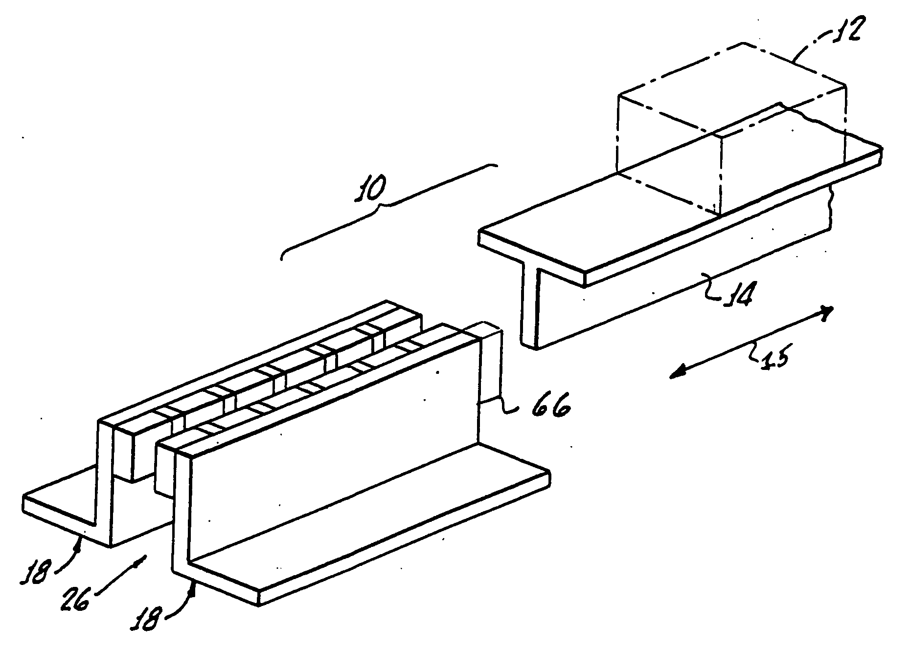
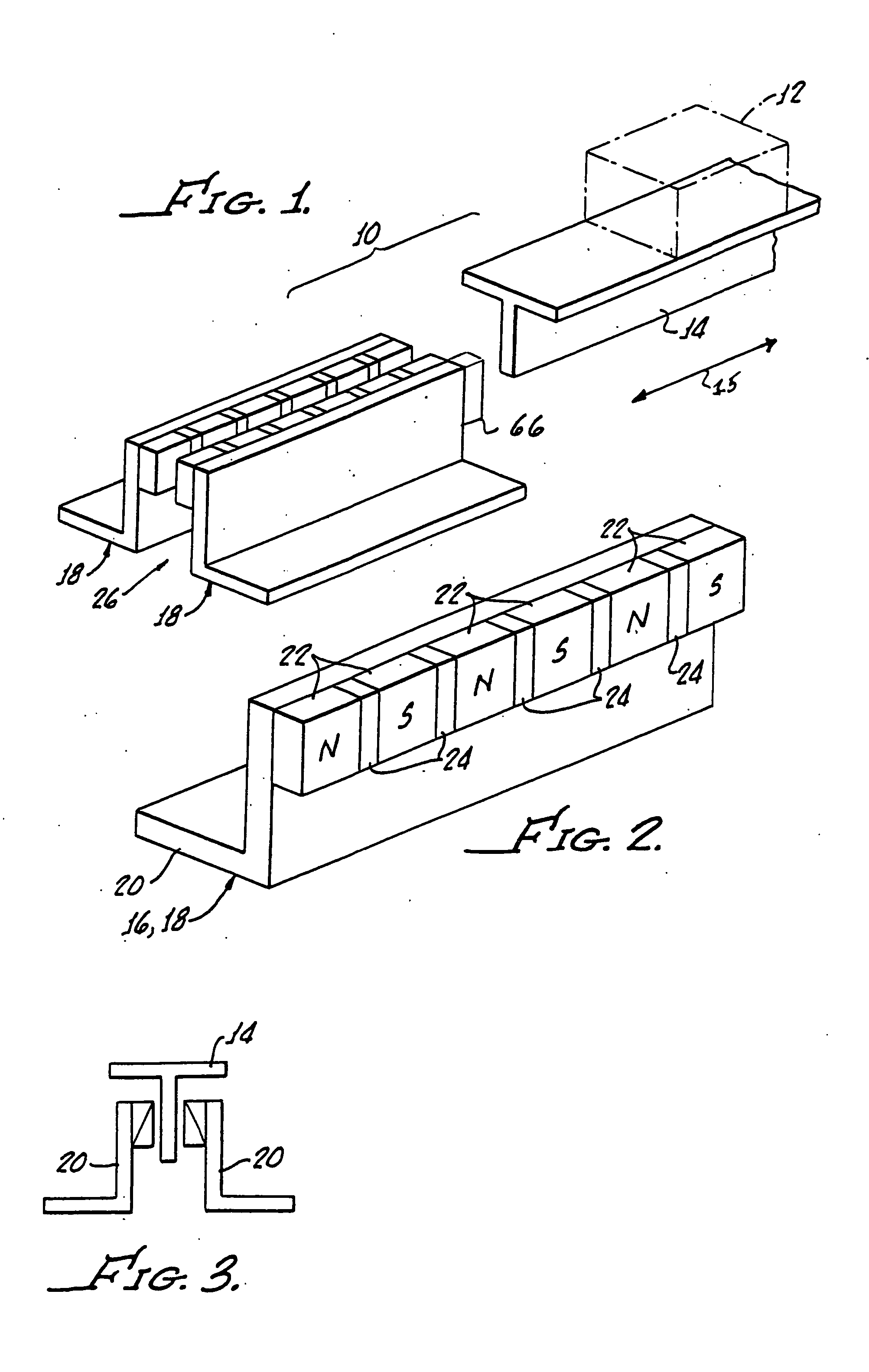
[0042] Although the above-described first embodiment includes movement of the object and fin past fixedly located magnet arrays, the magnet arrays can just as well be moved past a stationary object and fin. All that is needed to achieve the braking effect is relative movement between the magnets and fin. Since usually the object is moving, in that case the magnet arrays would be carried by the object and the fin fixedly mounted adjacent the path of movement. The choice of which technique to employ depends upon the particular application.

[0043] In its more general aspects, the invention can be advantageously employed for braking a large variety of moving objects. As an excellent example, eddy current braking for elevators could be highly advantageous as an emergency measure where normal operation has somehow been interfered with or disrupted. Also, many amusement park rides could benefit by having eddy current braking devices to retard excessive speed as the “ride” vehicle takes a co...

embodiment 400

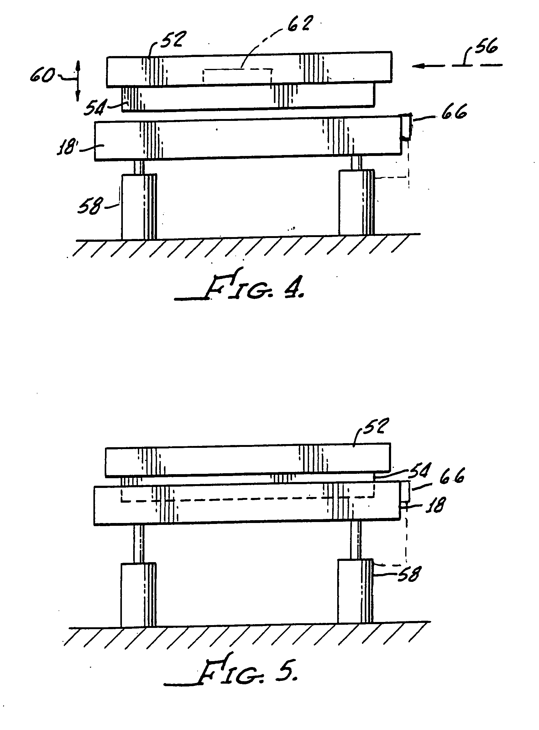
[0086] Alternatively, the array 460 may be spring 472 loaded in order to provide rotation of the array 466 as a function of velocity of the member 452 between the arrays 454, 460. This movement is akin to the linear movement of the array 408 hereinabove described in connection with the embodiment 400 of the present invention.

[0087] Turning on to FIG. 18, there is diagramed eddy current brake mechanism 500 generally including a diamagnetic or non-magnetic member 502 as hereinbefore described in connection with earlier embodiments along with a first movable linear array 504 of permanent magnets 506 and a second movable linear array 508 of permanent magnets 510 disposed in a spaced apart relationship for enabling passage of the member 502 therebetween.

[0088] The magnet arrays 504, 508 establish a plane 514, and an actuator, which may be pneumatic or electric 516, is coupled to the arrays 504, 508 as indicated by the dashed line 520 in a conventional manner for adjusting the eddy curre...


PUM


Abstract

An eddy current brake includes a diamagnetic member, a first support wall and a second support wall with the first and second linear arrays of permanent magnets disposed on the walls facing one another. Apparatus is provided for moving at least one of the walls in order to control eddy current induced in the member in the passage of the member therepast to adjust the braking force between the magnets and the member. Apparatus is also provided for causing the velocity of the member to change the braking force between the magnets and the member.

Description

[0001] The present application is a continuation-in-part of U.S. patent application Ser. No. 10 / 679,685 filed Sep. 15, 2003 which is a continuation-in-part of U.S. patent application Ser. No. 09 / 880,353 filed Jun. 13, 2001 now U.S. Pat. No. 6,659,237 B1 which is a continuation-in-part of U.S. patent application Ser. No. 09 / 447,206 filed Nov. 22, 1999 now U.S. Pat. No. 6,293,376.[0002] The present invention is generally related to permanent magnet linear brakes and is more particularly directed to an eddy current brake and magnet system for providing adjustable braking for movable apparatus, for example, rail support moving apparatus, go-cart moving apparatus, elevator moving apparatus, conveyer moving apparatus, roller coaster moving apparatus, and magnetically levitated vehicles or apparatus, among others. [0003] Heretofore, eddy current braking system for providing deceleration of moving apparatus have utilized physically fixed magnets which provided no opportunity to adjust braki...

Claims


Application Information

Patent Timeline
Patent Type & Authority Applications(United States)
IPC IPC(8): B60L7/10
CPCH02K49/046B61H7/083H02K2213/09
Inventor PRIBONIC, EDWARD M.THOMPSON, MARC T.
Owner MAGNETAR TECH
Why Eureka
Try Eureka