Method for operating a vehicle brake system

a brake system and vehicle technology, applied in the field of vehicle brake systems, can solve the problems of high intensity, low frequency vibration or noise, referred to as brake groan or creep groan, vibration that can produce an audible oscillation, etc., and achieve the effect of reducing the brake groan nois

Inactive Publication Date: 2010-09-30
GM GLOBAL TECH OPERATIONS LLC
View PDF2 Cites 69 Cited by
  • Summary
  • Abstract
  • Description
  • Claims
  • Application Information

AI Technical Summary

Benefits of technology

[0005]According to another embodiment, there is provided a method for operating a vehicle brake system. The method generally comprises the steps of: (a) gathering a vehicle speed, brake status information, and brake vibration data; (b) using the vehicle speed, brake status information, and the brake vibration data to determine if the vehicle brake system is producing brake groan noise; (c) if the vehicle brake system is producing brake groan noise, then making a first braking adjustment; (d) determining if the first braking adjustment is effective at reducing the brake groan noise; and (e) if the first braking adjustment is not effective at reducing the brake groan noise, then making a second braking adjustment.
[0006]According to another embodiment, there is provided a brake-by-wire vehicle brake system. The system generally comprises: a brake pedal sensor for providing brake pedal status information; one or more vibration sensor(s) for providing brake vibration data; an electronic brake control module (EBCM) coupled to the brake pedal sensor and to the vibration sensor(s); and one or more disk brake unit(s) having a brake pad and a brake rotor. The EBCM uses the brake pedal status information and the brake vibration data to determine if a brake vibration condition exists and, if so, generates a modified brake command signal that results in a braking adjustment by the disk brake unit(s).

Problems solved by technology

Applying the vehicle brakes while the vehicle is moving at a slow speed can sometimes result in a high intensity, low frequency vibration or noise that is commonly referred to as brake groan or creep groan.
When the slip-phase begins, the sudden energy burst results in a vibration that can produce an audible oscillation.

Method used


Image

  • Method for operating a vehicle brake system
  • Method for operating a vehicle brake system
  • Method for operating a vehicle brake system

Examples


Embodiment Construction

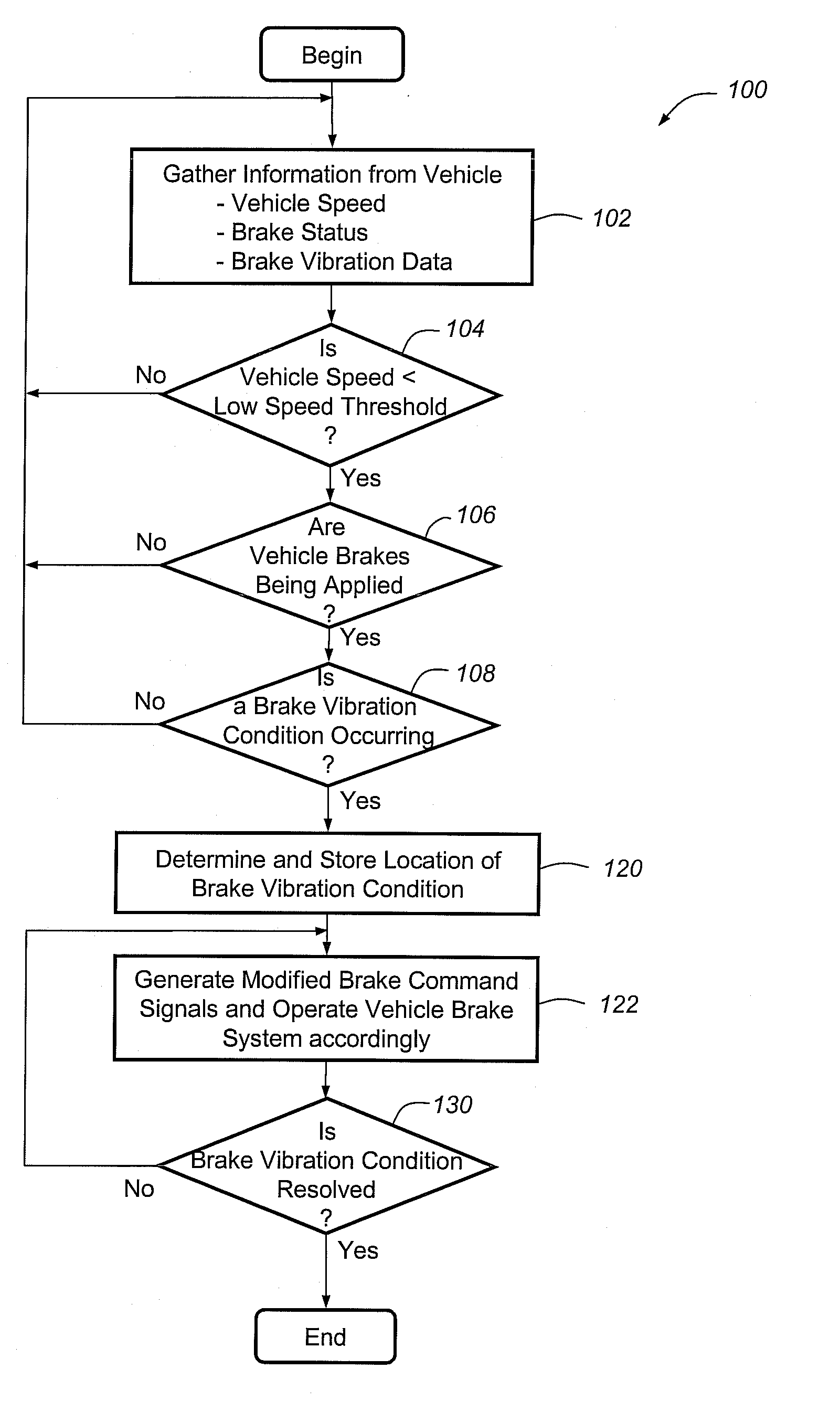
[0011]The method described herein reduces or mitigates the effects of vibration in a vehicle brake system, particularly those that can lead to brake groan or other unwanted noise. According to an exemplary embodiment, when a vehicle brake system 10 detects certain vibratory or other undesirable conditions, it makes slight braking adjustments (e.g., adjustments to fluid pressure, brake force, brake torque, etc.) in order to mitigate the brake groan. Although this method is particularly well suited for use with brake-by-wire systems, such as electrohydraulic braking (EHB) and electromechanical braking (EMB) systems, it should be appreciated that it may also be used with any number of other braking systems and is not limited to the disclosed embodiment. For example, the present method may be used with other brake-by-wire and non-brake-by-wire systems, regenerative and non-regenerative braking arrangements (e.g., those found in hybrid vehicles, electric vehicles, etc.), as well as other...


PUM


Abstract

A method for reducing or mitigating the effects of vibration in a vehicle brake system, particularly those that can lead to brake groan or other unwanted noise. According to an exemplary embodiment, when the vehicle brake system detects certain vibratory conditions, it makes slight braking adjustments (e.g., adjustments to fluid pressure, brake force, brake torque, etc.) that are aimed to address the brake groan. The vehicle brake system can then determine the effectiveness of the braking adjustments and, if need be, make additional braking adjustments. The method is particularly well suited for use with brake-by-wire systems, but can be used with a number of different vehicle braking systems.

Description

TECHNICAL FIELD[0001]The present invention generally relates to vehicle brake systems and, more particularly, to methods that mitigate vibration-related effects in a vehicle brake system.BACKGROUND[0002]Applying the vehicle brakes while the vehicle is moving at a slow speed can sometimes result in a high intensity, low frequency vibration or noise that is commonly referred to as brake groan or creep groan.[0003]Some skilled artisans believe that brake groan is caused by the ‘stick-slip’ effect, which involves a stick-phase where the brake lining and rotor are momentarily stuck and move together (no slippage at their interface) and a slip-phase when those two components break free of one another (slippage at their interface). Not wanting to be bound by any particular theory, it is believed that the time period of the stick-phase is variable and depends on factors such as speed, brake load, and system stiffness. When the slip-phase begins, the sudden energy burst results in a vibratio...

Claims


Application Information

Patent Timeline
Patent Type & Authority Applications(United States)
IPC IPC(8): G06F19/00G01M17/00
CPCB60T8/00B60T8/173F16D65/0012B60T17/221B60T2270/82B60T8/326
Inventor KINSER, CHRISTOPHER A.KRUEGER, ERIC E.
Owner GM GLOBAL TECH OPERATIONS LLC
Why Eureka
Try Eureka