a breather cap

A technology of vent caps and vent holes, which is applied in the field of vent caps and can solve problems such as vent cap damage

Active Publication Date: 2016-03-02
WORLD TRANSMISSION TECH TIANJIN SHARE LTD
View PDF5 Cites 0 Cited by
  • Summary
  • Abstract
  • Description
  • Claims
  • Application Information

AI Technical Summary

Problems solved by technology

[0006] The technical problem to be solved by the present invention is to provide a vent cap, which can solve the vent cap through its structural design, especially the vent cap used in harsh working conditions is easy to cause damage.

Method used


Image

  • a breather cap

Examples


Embodiment Construction

[0030] The core of the present invention is to provide a vent cap, the vent cap can achieve the purpose of solving the problem that the vent cap, especially the vent cap used in harsh working conditions, is easily damaged through its structural design.

[0031] In order to enable those skilled in the art to better understand the technical solutions of the present invention, the present invention will be further described in detail below in conjunction with the accompanying drawings and specific embodiments.

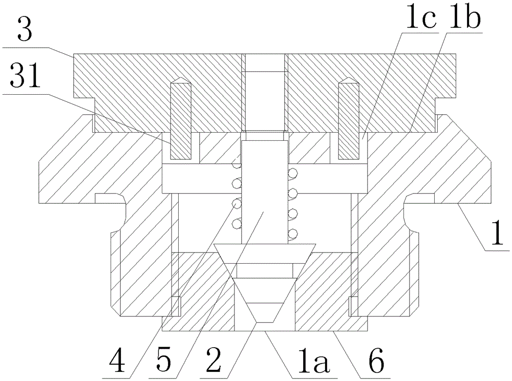
[0032] Please refer to figure 1 , figure 1 It is a structural schematic diagram of the ventilation cap in an embodiment of the present invention.

[0033] The present invention provides a vent cap, which is mainly used for pressure adjustment of a reducer, comprising: a vent cap main body 1 , a first blocking part 2 , a second blocking part 3 and a reset part 4 . The vent cap main body 1 is provided with an air inlet 1a and an air outlet 1b communicating with each other...


PUM


Abstract

The invention discloses a vent cap which comprises a vent cap main body, a first plugging piece, a second plugging piece and a resetting component. An air inlet and an air outlet which are communicated with each other are arranged on the vent cap main body, the air inlet is communicated with a vent of a reducer, the first plugging piece seals the air inlet, the second plugging piece seals the air outlet, and the resetting component is connected with the first plugging piece. The resetting component can provide resetting force for the first plugging piece, when the pressure in the reducer exceeds force exerted on the first plugging piece by the resetting component, the first plugging piece is ejected, and air in the reducer is guided out. When the pressure in the reducer is reduced, the first plugging piece and the second plugging piece are reset to seal the air inlet and the air outlet again. By means of the structural design, the vent cap can conduct pressure adjustment on the reducer, and a purpose of solving the problem that the vent cap is easy to damage in severe working condition environment is achieved.

Description

technical field [0001] The invention relates to the technical field of valve components for fluid communication, in particular to a vent cap. Background technique [0002] In the prior art, some equipment with high-speed running motion, such as a reducer, etc., the internal gas will have a large property change, and the reducer is taken as an example below. [0003] The reducer is a power transmission mechanism that uses the speed converter of the gear to reduce the number of revolutions of the motor (motor) to the desired number of revolutions and obtain a larger torque mechanism. The reducer is generally used to decelerate the electric motor, internal combustion engine or other high-speed running equipment. Since the electric motor or internal combustion engine has a high speed, the reducer will also have a high speed. As a common sense, when the reducer is in a non-working state (stationary), the temperature of the reducer is close to the temperature of the surrounding a...

Claims


Application Information

Patent Timeline
Patent Type & Authority Patents(China)
IPC IPC(8): F16H57/027F16K17/04F16K17/164
Inventor 胡炜
Owner WORLD TRANSMISSION TECH TIANJIN SHARE LTD
Why Eureka
Try Eureka