Method for testing dynamic performance of star sensor
A star sensor and dynamic performance technology, applied in the direction of instruments, measuring devices, etc., can solve the problems of not being able to accurately simulate the actual position of stars, not being able to assess the accuracy of the star sensor, and being difficult to assess the polarity of the star sensor, etc., to achieve Reduce test cost, reduce test equipment, save manpower and material resources
- Summary
- Abstract
- Description
- Claims
- Application Information
AI Technical Summary
Problems solved by technology
Method used
Image

Examples
Embodiment 1
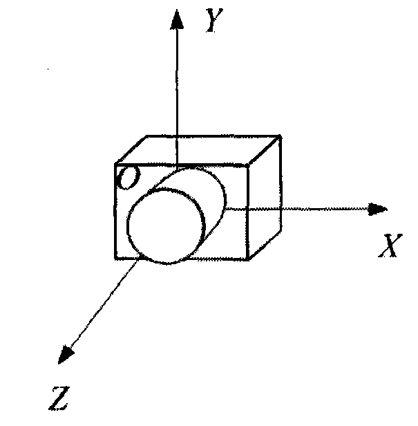
[0045] Such as figure 2 As shown, the star sensor image space coordinate system is defined as: the origin 0 is located at the center of the star sensor sensor (CCD), facing the star sensor lens, the X axis is parallel to the CCD plane to the right, and the Y axis is parallel to the CCD plane upward , the Z-axis is vertical and the CCD faces outward.
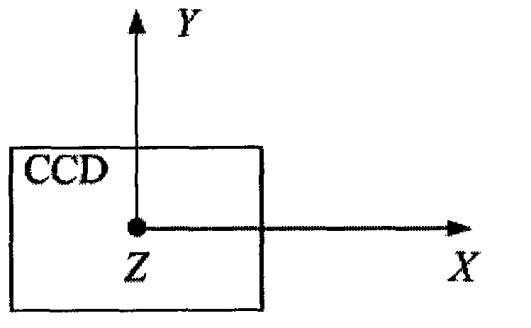
[0046] That is to say, the polarity of the star sensor is as follows image 3 Shown:
[0047] Suppose the attitude angle of the star sensor rotating around the X axis is called the yaw angle, the attitude angle around the Y axis is called the pitch angle, and the attitude angle around the Z axis is called the roll angle.
[0048] Since the right ascension and declination of the star catalog loaded in the star sensor are the coordinate system of the geocentric inertial coordinate system (that is, the J2000.0 coordinate system), the output attitude of the star sensor is the star sensor image space coordinate system and J2000.0 ...
Embodiment 2
[0083] Main performance indicators of star sensor:
[0084] Field of View: 14°×14°
[0085] Area array: 1024×1024
[0086] Detection magnitude: 6My
[0087] Data update rate: 15Hz
[0088] Three-axis angular velocity error of turntable: 0.1(″ / s)
[0089] We selected a certain type of star sensor and a certain type of automatic three-axis turntable. Before the experiment, the star sensor was installed on the three-axis turntable so that the three axes of the star sensor and the three axes of the turntable completely overlapped (this experiment is for It is convenient for testing, the X-axis, Y-axis, and Z-axis of the turntable coincide with the X-axis, Y-axis, and Z-axis of the star sensor respectively), this experimental test is divided into static test and dynamic test.
[0090] (1) Static test
[0091] Adjust the turntable so that the Z-axis of the turntable points to the North Pole of the earth, and rotate the Z-axis of the turntable so that the X-axis of the turntable p...
Embodiment 3
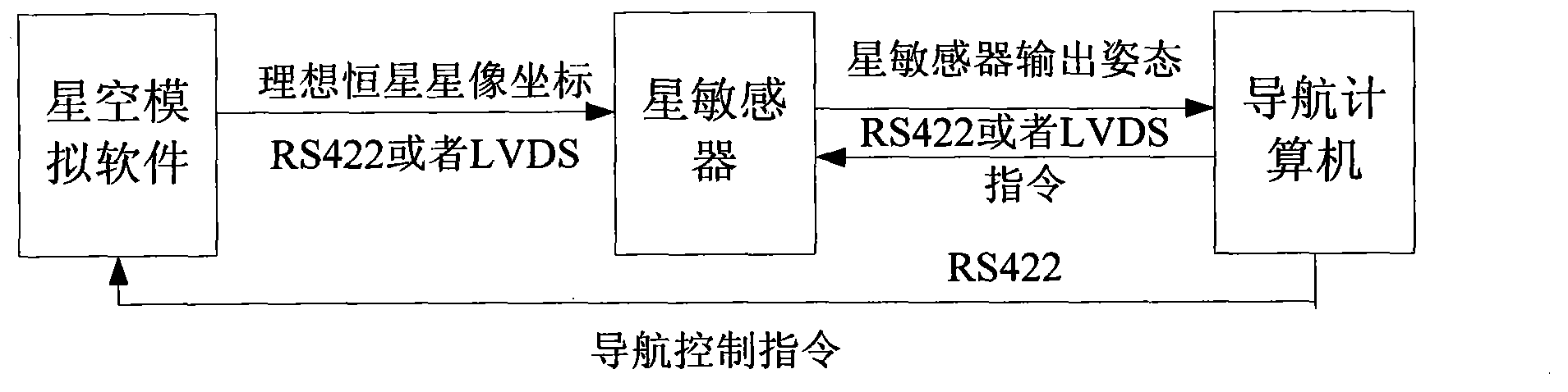
[0095] Such as Figure 8 It is an embodiment of a method for testing the dynamic performance of a star sensor. The test equipment includes a three-axis turntable 3 (the accuracy of the three-axis angular velocity of the three-axis turntable is 0.1 (″ / s)) and a test computer 1. The test computer 1 adopts PC, the PC receives the attitude quaternion output by the star sensor in real time, and the real-time display program is written in VC++6.0. This program can not only display the required error curve in real time, but also save it in real time. First, the star sensor 2 Place it on the three-axis turntable 3, use theodolite to adjust the three-axis turntable 3, make the X-axis and Z-axis point to the J2000. Move at a certain angular velocity, check the connection and then power on the star sensor. After the star sensor is powered on, it will perform a self-inspection. After the self-inspection is successful, take a star map, extract the position of the star image, recognize the ...
PUM
 Abstract
Description
Claims
Application Information
 - R&D Engineer
- R&D Manager
- IP Professional
- Industry Leading Data Capabilities
- Powerful AI technology
- Patent DNA Extraction
Browse by: Latest US Patents, China's latest patents, Technical Efficacy Thesaurus, Application Domain, Technology Topic.
© 2024 PatSnap. All rights reserved.Legal|Privacy policy|Modern Slavery Act Transparency Statement|Sitemap