A single-end distance measurement method for single-phase ground fault of transmission line

A single-phase ground fault and transmission line technology, applied in the fault location and other directions, can solve the problems of ranging accuracy transition resistance, high sampling rate requirements, and high application costs, and achieves easy program implementation, simple ranging principle, and measurement fast effect

Active Publication Date: 2015-08-26
STATE GRID CORP OF CHINA +3
View PDF8 Cites 0 Cited by
  • Summary
  • Abstract
  • Description
  • Claims
  • Application Information

AI Technical Summary

Problems solved by technology

The traveling wave method uses the transmission properties of fault transient traveling waves to perform single-ended fault location. The distance measurement accuracy is high, and it is not affected by the operation mode and excessive resistance. However, it requires a high sampling rate and requires a special wave recording device. high cost
The impedance method uses the voltage and current after the fault to calculate the fault loop impedance, and performs single-ended fault distance measurement according to the characteristic that the line length is proportional to the impedance, which is simple and reliable, but the distance measurement accuracy is seriously affected by the transition resistance, especially when the transition resistance is large , the single-ended fault location results will seriously deviate from the real fault distance, and even exceed the total length of the transmission line, making the single-ended fault location results lose their reference value, and cannot provide accurate and effective fault location information for power system fault line inspectors, which is not conducive to Quickly locate the fault location and quickly eliminate the fault

Method used


Image

  • A single-end distance measurement method for single-phase ground fault of transmission line
  • A single-end distance measurement method for single-phase ground fault of transmission line
  • A single-end distance measurement method for single-phase ground fault of transmission line

Examples


Embodiment Construction

[0014] The technical solution of the present invention will be further described in detail according to the accompanying drawings.

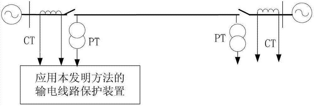
[0015] figure 1 It is a schematic diagram of the line transmission system applying the present invention. figure 1 Among them, PT is a voltage transformer, and CT is a current transformer. The protection device samples the voltage waveform of the voltage transformer PT and the current waveform of the current transformer CT at the installation place of the transmission line protection to obtain the instantaneous value of the voltage and current, and calculates the instantaneous value of the voltage and current obtained by sampling using the Fourier algorithm Fault phase voltage at transmission line protection installation , fault phase negative sequence current , fault phase current and zero sequence current , as the input quantity; among them, φ=A phase, B phase, C phase.

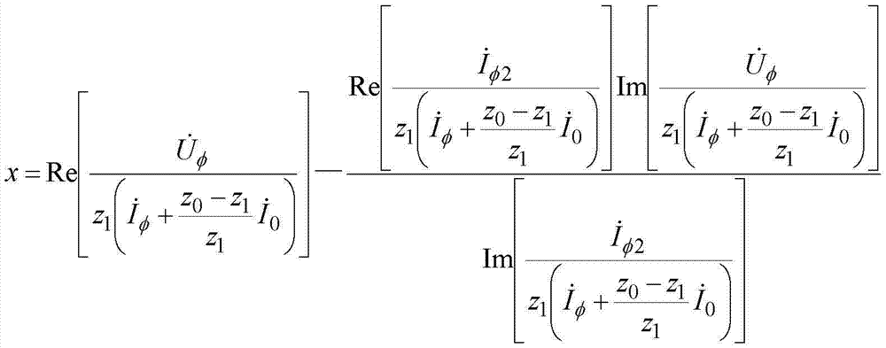
[0016] The protection device uses the transmission line to prot...


PUM


Abstract

The invention discloses a single-end distance measurement method for an electric transmission line single-phase earth fault. The method comprises the following steps: calculating equivalent resistance by using fault phase electric quantity in the electric transmission line protection installing place, multiplying the equivalent resistance by fault phase negative sequence current to acquire the single-phase earth fault point voltage, calculating a real part of a ratio between single-phase earth fault point voltage and electric transmission line voltage drop per unit length to acquire an additional fault distance caused by transition resistance, and using the real part of the ratio to subtract the additional fault distance so as to acquire a fault distance from the electric transmission line protection installing place to the single-phase earth fault point. According to the method, the problem about the effect of transition resistance on single-end fault distance measurement accuracy is solved, higher distance measurement accuracy is achieved in case of electric transmission line single phase high resistance ground fault, the distance measurement principle is simple, the process is easy to realize, the fault distance is directly calculated without adopting the search algorithm, the distance measurement speed is high, and the instantaneity is high.

Description

technical field [0001] The invention relates to the technical field of electric power system relay protection, in particular to a single-end distance measuring method for a single-phase grounding fault of a power transmission line. Background technique [0002] The single-end fault location method of transmission lines only uses the electrical quantity at one end of the transmission line for fault location, does not require communication and data synchronization equipment, has low operating costs and stable algorithms, and has been widely used in transmission lines. [0003] Single-ended fault location methods are mainly divided into traveling wave method and impedance method. The traveling wave method uses the transmission properties of fault transient traveling waves to perform single-ended fault location. The distance measurement accuracy is high, and it is not affected by the operation mode and excessive resistance. However, it requires a high sampling rate and requires ...

Claims


Application Information

Patent Timeline
Patent Type & Authority Patents(China)
IPC IPC(8): G01R31/08
Inventor 林富洪曾惠敏
Owner STATE GRID CORP OF CHINA
Why Eureka
Try Eureka