
Image display apparatus

An image display device and image signal technology, which can be used in projection devices, image communication, and image reproducers using projection devices, etc., and can solve problems such as changes in white balance of display screens

Inactive Publication Date: 2013-08-14
HITACHI-LG DATA STORAGE
View PDF5 Cites 13 Cited by
  • Summary
  • Abstract
  • Description
  • Claims
  • Application Information

AI Technical Summary

Problems solved by technology

[0003] However, in semiconductor lasers used in compact projection projectors, the light intensity / forward current characteristics change according to temperature, so there is a problem that the white balance of the display screen changes

Method used


Image

  • Image display apparatus
  • Image display apparatus
  • Image display apparatus

Examples


Embodiment 1

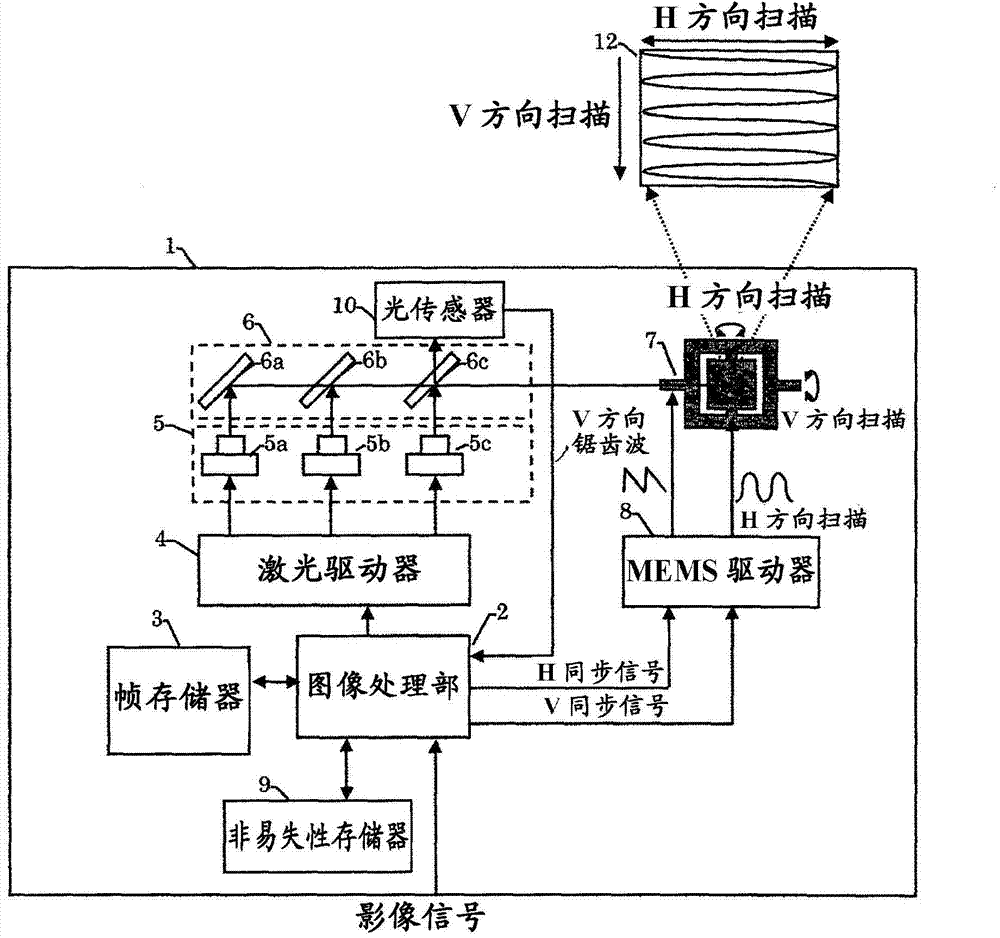
[0025] figure 1 A configuration example of a projection projector using MEMS in this embodiment is shown. The projection projector 1 includes an image processing unit 2, a frame memory 3, a laser driver 4, a laser 5, a mirror 6, MEMS 7, a MEMS driver 8, a nonvolatile memory 9, an optical sensor 10, a temperature sensor 11, and a display image 12 . The image processing unit 2 generates an image signal to which various corrections have been applied to an externally input video signal, and generates a horizontal synchronization signal and a vertical synchronization signal synchronized therewith. In addition, the image signal to the laser driver 4 is controlled based on the amount of light acquired from the optical sensor 10, and the white balance is adjusted so as to be constant. The details will be described later. Here, various corrections refer to correction of image distortion due to scanning of the MEMS 7 and the like. In detail, image distortion occurs due to difference...

Embodiment 2

[0050] Next, Example 2 in the present invention will be described. Figure 8 It is a figure which shows the operation example of this embodiment. The difference from the first embodiment is the setting method of the reference value in the reference value unit 24. Other than that, it is the same as that of the first embodiment, so detailed description is omitted.

[0051] In the first embodiment, the reference values ​​stored in the reference value unit 24 are two points of R1 and R2. When the reference value is only 2, the input image data ( D1 , D2 ) equal to the reference value may infrequently enter, and the correctable timing may be limited. Therefore, in the second embodiment, all of the input image data entering between R1 and R2 is used for the reference value. That is, if Figure 8 Like F1 of F1, all write addresses A1~An corresponding to the input image data D1 to Dn (n is an integer) between the entry reference values ​​R1 and R2 are obtained, and the output image...

Embodiment 3

[0054] Next, Example 3 in the present invention will be described. Figure 9 It is a figure which shows the operation example of this embodiment. The difference from Example 1 and Example 2 is that the image data is positively superimposed on the image data on the assumption that the range of the reference value part 24 does not enter the image data, and other than that of Example 1 and Example 2. are the same, so detailed description is omitted.

[0055] In Example 2, the range of the reference value in the reference value unit 24 is between R1 and R2. There is also a possibility that the input image data does not frequently fall between the reference values, and there is a possibility that the correctable timing is limited. Therefore, in the third embodiment, if the reference value does not fall between R1 and R2 within a certain period of time, the reference values ​​D1 and D2 are superimposed on the input image data D3. That is, if Figure 9 Like the F1 and F2 of F1 an...


PUM


Abstract

In an image display apparatus which projects and displays an image by scanning emitted light from light sources by a reflective mirror, a correction unit calculates a threshold value and a slope efficiency of a light amount vs. current characteristic of each of the plurality of light sources, from a first light amount value obtained by measuring a light amount when an input image signal agrees with a first reference signal level and a second light amount value obtained by measuring a light amount when the input image signal agrees with a second reference signal level; and corrects, when a calculation result of the threshold value and the slope efficiency varied after a predetermined time, a threshold current and also make a correction so that a light amount ratio of the light sources becomes the same as an initial value of a slope efficiency ratio.

Description

technical field [0001] The present invention relates to an image display device using MEMS (Micro Electro Mechanical Systems, Micro Electro Mechanical Systems) or the like. Background technique [0002] In recent years, small projection projectors using MEMS and semiconductor laser light sources have become popular. For example, Patent Document 1 discloses a projector that projects an image by modulating a laser light source while scanning a biaxial MEMS mirror in the horizontal and vertical directions. [0003] However, in semiconductor lasers used in compact projection projectors, the light intensity / forward current characteristics change with temperature, so there is a problem that the white balance of a display screen changes. Patent Document 2 discloses a method of compensating for a temperature change of a semiconductor laser. [0004] [Patent Document 1] Japanese Unexamined Patent Publication No. 2006-343397 [0005] [Patent Document 2] Japanese Unexamined Patent P...

Claims


Application Information

Patent Timeline
Patent Type & Authority Applications(China)
IPC IPC(8): G02B26/10G03B21/14H04N9/31
CPCG03B21/14H04N9/31G02B26/10H04N9/3135H04N9/3182
Inventor 春名史雄小堀智生
Owner HITACHI-LG DATA STORAGE
Learn More