
an electronic fuse

An electronic fuse and power technology, applied in electrical components, circuit devices, emergency protection circuit devices, etc., can solve the problems of increasing circuit complexity, failure, lack of inverse time delay characteristics, and high device cost, and achieves improved maintenance. The effect of efficiency, simple structure and low cost

Inactive Publication Date: 2015-08-12
CHONGQING UNIV
View PDF4 Cites 0 Cited by
  • Summary
  • Abstract
  • Description
  • Claims
  • Application Information

AI Technical Summary

Problems solved by technology

However, since the device uses a two-stage switch structure, the complexity of the circuit and the possible failure links are increased, and the cost of the device is also high; more importantly, the device does not have anti-delay characteristics. It is also not suitable for circuits that need to use the anti-delay characteristic

Method used


Image

  • an electronic fuse
  • an electronic fuse
  • an electronic fuse

Examples


Embodiment Construction

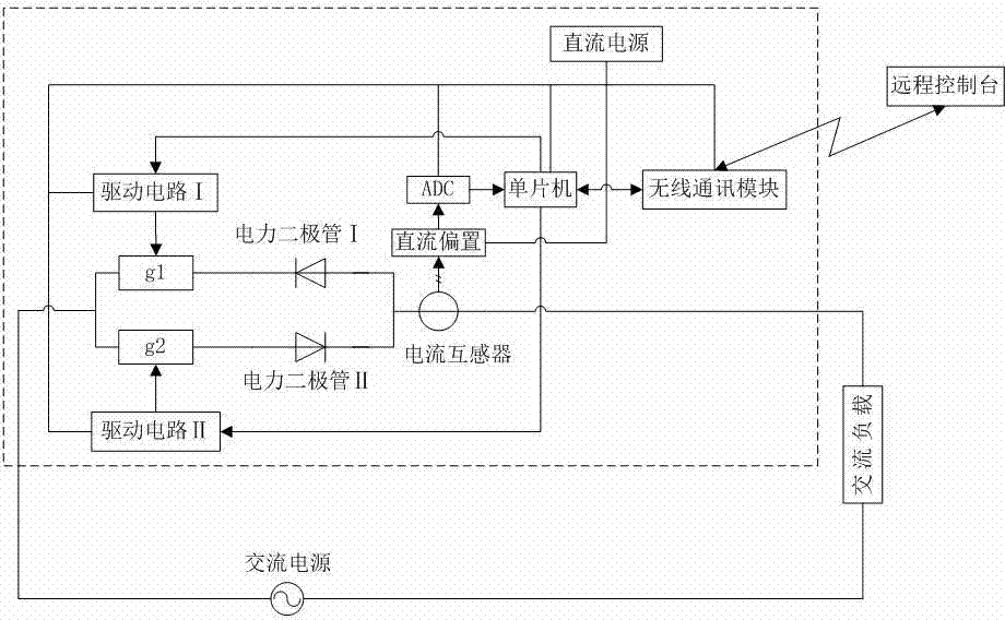
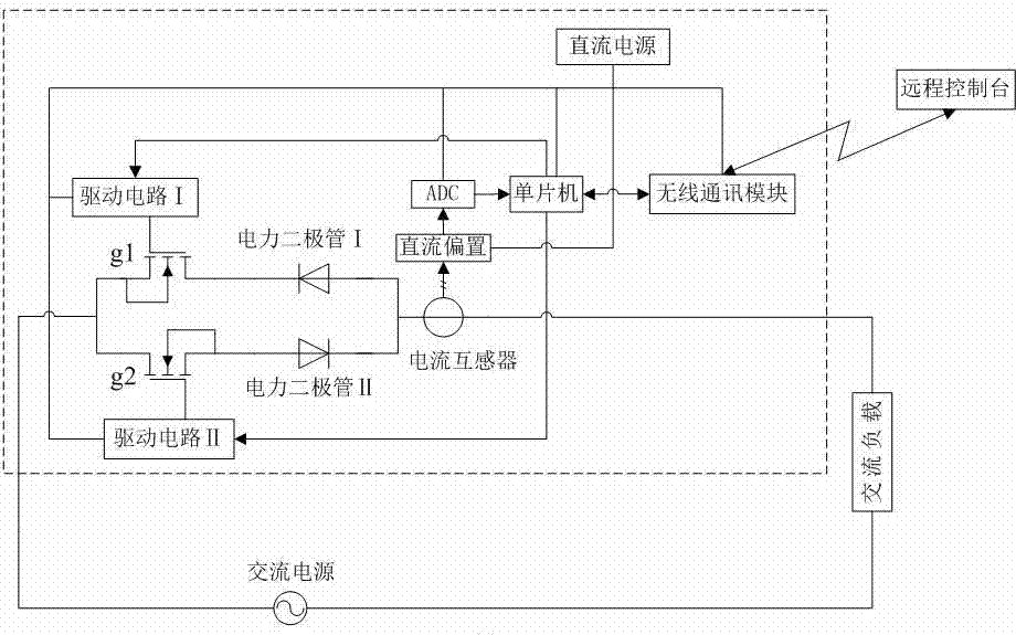
[0012] An electronic fuse (reference figure 1 ), one end of it is connected to the AC power supply, and the other end is connected to the AC load. The circuit of the electronic fuse includes a power FET and its drive circuit. In the present invention, there are two groups of the power field effect transistor and its driving circuit, all of which are controlled by the same single-chip microcomputer. Circuit II to the gate of the power field effect transistor IIg2; the source of the power field effect transistor I and the drain of the power field effect transistor II are both connected to the AC power supply, and the cathode of a power diode I is connected to the On the drain of the power field effect transistor I, there is an anode of a power diode II connected to the source of the power field effect transistor II; the anode of the power diode I and the cathode of the power diode II are connected to each other and passed through A current transformer is connected with the AC l...


PUM


Abstract

The invention discloses an electronic fuse. The electronic fuse consists of two groups of power field-effect transistors, and driving circuits, two power diodes, current transformers, direct-current bias modules, analog-to-digital conversion modules, single-chip microcomputers, remote control tables, wireless communication modules and direct-current power supplies of the two groups of the power field-effect transistors. Compared with the current various electronic fuses, the electronic fuse has the advantages of capability of being repeatedly used and failure remote alarming, remote control and failure positioning functions. Compared with the electronic fuse with remote alarming and remote control functions, the electronic fuse has the advantages of simple structure and low cost. The electronic fuse is really suitable for being used in a circuit which requires the characteristic of inverse time lag.

Description

technical field [0001] The present invention relates to electronic fuses. Background technique [0002] A fuse is a device that is connected in series in a circuit to provide short-circuit protection or severe overload protection for a circuit (including electrical appliances, power supplies, etc.) by fusing the "open circuit" of the fuse. In order to save the trouble of replacing the fuse (such as the fuse commonly known as "fuse") afterwards, people have invented an electronic fuse that uses a reset button to replace the fuse. The components used to replace the fuse mainly include power field Effect tube (and necessary drive circuit). However, many inventions or products called "electronic fuses" in the prior art are not actually fuses, but just a kind of circuit breaker, because they do not have the anti-delay characteristic of "fuses" , Therefore, these products called "electronic fuses" cannot replace ordinary fuses in circuits that need to take advantage of their ant...

Claims


Application Information

Patent Timeline
Patent Type & Authority Patents(China)
IPC IPC(8): H02H3/06H02H3/04H02H3/08
Inventor 杜雄李福陈逍潇
Owner CHONGQING UNIV
Learn More