Enhanced wireless charging system
A wireless charging and enhanced technology, applied in electromagnetic wave systems, current collectors, electric vehicles, etc., can solve the problems that ultra-thin mobile phones are difficult to achieve, unfavorable for the promotion of wireless charging technology, etc., to achieve free-position charging, increase charging distance, space saving effect
- Summary
- Abstract
- Description
- Claims
- Application Information
AI Technical Summary
Problems solved by technology
Method used
Image

Examples
Embodiment 1
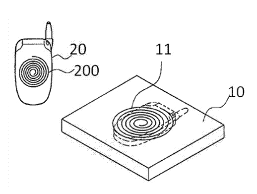
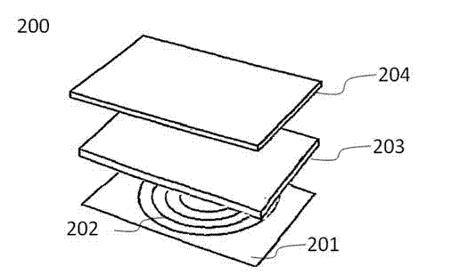
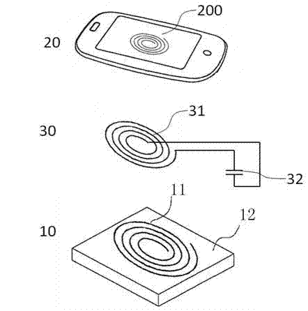
[0054] refer to image 3 , the wireless transmitting part 10 includes a transmitting coil 11 and a first ferrite 10, the first ferrite 10 is arranged below the transmitting coil 11, and the first ferrite 10 connects the transmitting coil 11 and other metals in the wireless charging device The components are spaced apart, and the first ferrite 10 is used to prevent metal components arranged in the wireless charging device from affecting the transmitting coil 11 to generate magnetic flux. The relay part 30 includes a relay coil 31 and a circuit part. The circuit part includes a capacitor 32 . The two ends of the capacitor 32 are connected to the two ends of the relay coil 31 to form a loop. The wireless receiving part 20 includes a receiving coil 202 and a second ferrite 203, the wireless receiving part 20 is arranged in the charged device, the charged device includes a battery 204, and the second ferrite 203 is arranged in the receiving coil 202 and the battery 204 between; th...
Embodiment 2
[0062] This embodiment is an improvement made on the basis of Embodiment 1. In this example, the wireless transmitting part 10 includes two transmitting coils, such as Figure 9 shown. The two transmitting coils are respectively the first transmitting coil 111 and the second transmitting coil 112 , and the first transmitting coil 111 and the second transmitting coil 112 are arranged side by side above the first ferrite 12 . The relay coil 31 is located above the middle of the first transmitting coil 111 and the second transmitting coil 112 . In this example, if Figure 10 As shown, the circuit part 33 connected to both ends of the relay coil 31 is provided with a switch 34 and a control part 35 in addition to the capacitor 32 . In this example, the relay coil 31 has a double function, and can be used as a backup transmitting coil, or can be used alone to realize the function of the transmitting coil. Except for the above-mentioned improvements, the rest of this embodiment i...
Embodiment 3
[0069] This embodiment is an improvement made on the basis of Embodiment 1 and Embodiment 2, such as Figure 11 As shown, this example includes two relay parts and one transmitting coil, and each relay part includes the circuit part as described in Embodiment 2, and the transmitting coil 11 is located below the middle of the two relay coils 31, The relay coil has dual functions of a transmitting coil and a relay coil, and is selected by the circuit part 33 . Except for the above-mentioned improvements, the rest of this embodiment is the same as the first embodiment. This embodiment realizes free charging at more locations.
[0070] The working principle of this embodiment is as follows:
[0071] refer to Figure 11 , when the position of the receiving coil is above the transmitting coil 11, such as Figure 11 Above position A shown in , the transmitting coil 11 receives the current from the signal source, the control circuit 35 controls the switch 34 to turn off, and the c...
PUM
 Abstract
Description
Claims
Application Information
 - R&D
- Intellectual Property
- Life Sciences
- Materials
- Tech Scout
- Unparalleled Data Quality
- Higher Quality Content
- 60% Fewer Hallucinations
Browse by: Latest US Patents, China's latest patents, Technical Efficacy Thesaurus, Application Domain, Technology Topic, Popular Technical Reports.
© 2025 PatSnap. All rights reserved.Legal|Privacy policy|Modern Slavery Act Transparency Statement|Sitemap|About US| Contact US: help@patsnap.com