A method and apparatus for wireless charging
A wireless charging and radio wave technology, applied in the electromagnetic field, can solve problems such as adverse effects on human health, lack of uniform standards, and low transmission efficiency, and achieve the effects of increasing the distance of wireless charging, being easy to put into use, and having a wide application prospect
- Summary
- Abstract
- Description
- Claims
- Application Information
AI Technical Summary
Problems solved by technology
Method used
Image
Examples
Embodiment 1
[0057] This embodiment simulates the effect of radio wave charging when an electromagnetic cavity is applied only at the transmit and receive coils.
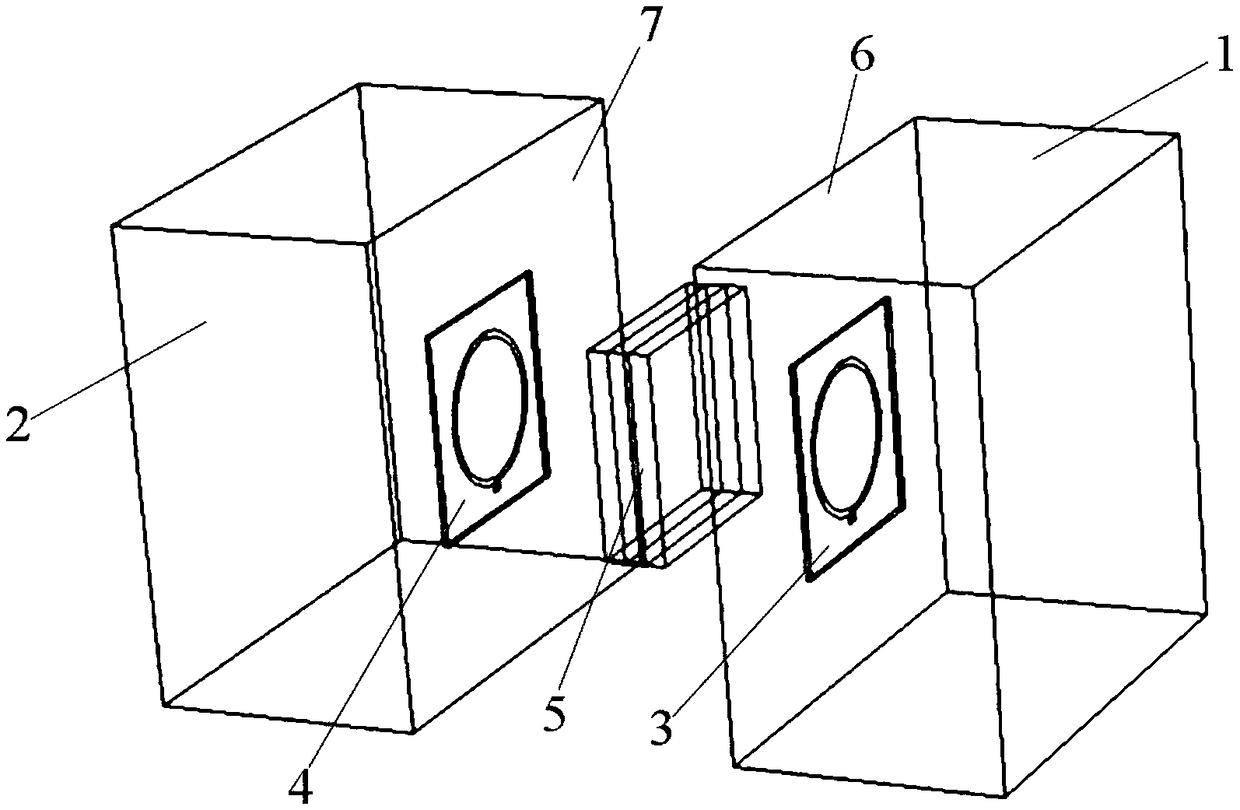
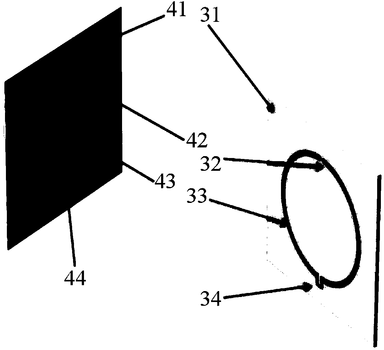
[0058] The inner and outer radii of the transmitting coil 3 and the receiving coil 4 are both 3.3cm and 3.6cm, and the inductance element is 66nH, and the coils are fixed on a PTFE plate with a thickness of 0.2cm and 10cm×10cm. The transmission frequency is taken as the resonant frequency of the LC resonant circuit, which is 915MHz, and the transmitting coil and the receiving coil are placed face to face with a distance of 16cm. Based on the numerical simulation software COMSOL Multiphysics, it can be simulated that the charging efficiency of radio waves at this time is only 0.23, where , the charging efficiency is represented by the ratio of the induced voltage of the receiving coil to the excitation voltage of the transmitting coil.
[0059] The electromagnetic wave working mode is modulated into a transverse electromagnetic w...
Embodiment 2
[0064] This embodiment simulates the charging effect when the dielectric plate 5 is provided only during radio wave transmission.
[0065] Get the same transmitting coil 3 and receiving coil 4 as in Embodiment 1, and insert a dielectric plate 5 with a three-layer symmetrical structure between them, and the dielectric plate 5 can be arranged on the output end face of the transmitting coil 3 and / or on the receiving coil 4 on the receiving end. According to the principle of Fabry-Perot resonance and combined with the coil parameters mentioned above, the size of each dielectric plate is 10cm×10cm, the thickness is 1cm, and the relative dielectric properties of the first and third layers of dielectric materials are taken The constant is 50, and the relative permittivity of the intermediate dielectric material is 60. At this time, the charging efficiency of radio waves obtained through simulation is 0.49, which is also much higher than the original charging efficiency (0.23).
[00...
Embodiment 3
[0068] This embodiment simulates the charging effect when the first electromagnetic resonant cavity 1 , the second electromagnetic resonant cavity 2 and the dielectric plate 5 are applied simultaneously.
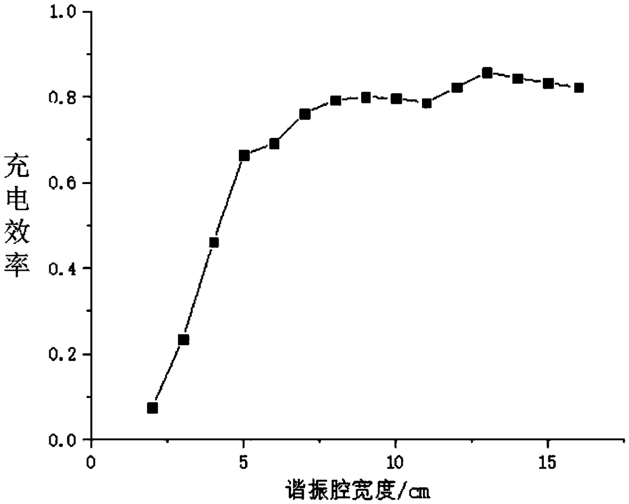
[0069] Get the same pair of transmitting coils 3 and receiving coils 4 in Example 1, consider the relationship between the charging efficiency and the thickness of the electromagnetic resonant cavity, get the thickness of the first electromagnetic resonant cavity 1 and the second electromagnetic resonant cavity 2 to be 13cm, and the dielectric The size parameters of the plate are the same as those in Example 2. At this time, the charging efficiency obtained by simulation can reach 0.89, and the corresponding electric field distribution diagram is as follows Figure 7 As shown, it can be seen that the electric field near the receiving coil is significantly enhanced.
[0070] The wireless charging method of the present invention uses radio wave technology, by applying an elect...
PUM
 Abstract
Description
Claims
Application Information
 - R&D
- Intellectual Property
- Life Sciences
- Materials
- Tech Scout
- Unparalleled Data Quality
- Higher Quality Content
- 60% Fewer Hallucinations
Browse by: Latest US Patents, China's latest patents, Technical Efficacy Thesaurus, Application Domain, Technology Topic, Popular Technical Reports.
© 2025 PatSnap. All rights reserved.Legal|Privacy policy|Modern Slavery Act Transparency Statement|Sitemap|About US| Contact US: help@patsnap.com


