Motor with oil storage function

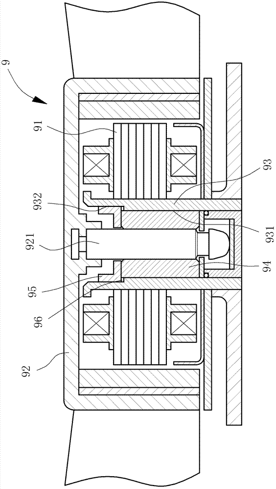
A motor and function technology, which is applied in the field of motors with oil storage function, can solve the problems of increasing the manufacturing cost of the existing motor 9, reducing the service life of the motor 9, and running unsmoothly.

Active Publication Date: 2013-08-14
SUNONWEALTH ELECTRIC MACHINE IND
View PDF8 Cites 0 Cited by
  • Summary
  • Abstract
  • Description
  • Claims
  • Application Information

AI Technical Summary

Problems solved by technology

[0005] The aforementioned existing motor 9 must embed the positioning ring 95 inside the shaft tube 93 so as to cooperate with the larger inner diameter hole 932 of the shaft tube 93 and the bearing 94 to form the oil storage tank 96, and prevent lubricating oil from However, since the oil storage tank 96 is formed inside the shaft tube 93, when the shaft tube 93 is embedded with the positioning ring 95, the positioning ring 95 easily occupies the inside of the shaft tube 93 Too much space relatively causes the oil storage space of the oil storage tank 96 to be compressed. When the oil storage space of the oil storage tank 96 is insufficient, it cannot accommodate enough lubricating oil. Therefore, after the existing motor 9 is used for a long time, it will It is easy to cause insufficient lubricating oil, and when the spindle 921 rotates relative to the bearing 94, it is easy to cause problems such as poor operation or failure to operate, thereby reducing the service life of the existing motor 9
[0006] Moreover, because the shaft tube 93 of the existing motor 9 is provided with the positioning ring 95, in addition to causing inconvenience in assembly, it also causes an increase in the number of assembly components of the existing motor 9. Therefore, the relative increase in the existing motor 9 manufacturing cost, so it is necessary to improve

Method used


Image

  • Motor with oil storage function
  • Motor with oil storage function
  • Motor with oil storage function

Examples


Embodiment Construction

[0049] In order to make the above-mentioned and other objects, features and advantages of the present invention more comprehensible, the preferred embodiments of the present invention are specifically cited below, together with the accompanying drawings, as follows:

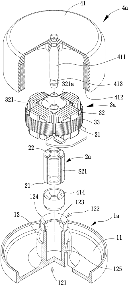
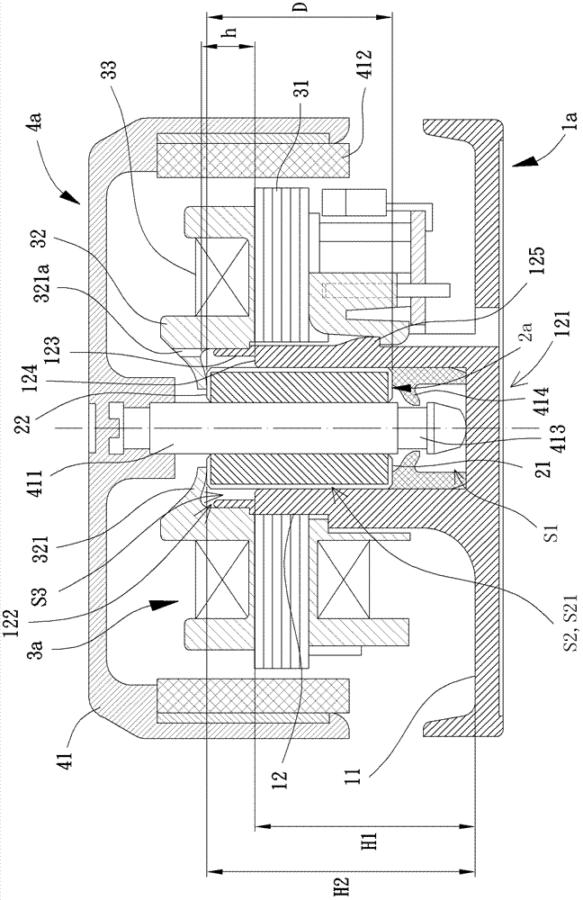
[0050] Please refer to figure 2 and 3 As shown, the motor with oil storage function according to the first embodiment of the present invention includes a base 1a, a bearing 2a, a stator assembly 3a and a rotor 4a. The base 1a can be accommodated and combined with the bearing 2a, the stator assembly 3a is combined with the base 1a, and the rotor 4a is rotatably combined with the bearing 2a.

[0051] The base 1a of the first embodiment of the present invention includes a base plate portion 11 and a shaft tube portion 12, and the shaft tube portion 12 is provided with a closed end 121 and an open end 122 opposite to each other, such as image 3 As shown, the closed end 121 of the shaft tube portion 12 is connecte...


PUM


Abstract

The invention discloses a motor with oil storage funciton. The motor includes a base, a bearing, a stator unit and a rotor. The base includes a shaft tube portion having a closed end and an open end. The bearing is received in the shaft tube portion of the base. The stator unit is fixed to the base and has an insulation unit. The insulation unit has a blocking portion extending towards the open end of the shaft tube portion. The rotor includes a hub having a shaft and a permanent magnet. The shaft is rotatably coupled with the bearing, and an air gap is formed between the permanent magnet and the stator unit. The blocking portion of the insulation unit, the shaft tube portion and the bearing jointly form an enlarged oil chamber at the open end of the shaft tube portion. With the above design, the shaft tube portion can have more space to form an oil-storing structure for accommodating more lubricating oil.

Description

technical field [0001] The invention relates to a motor, especially a motor with oil storage function. Background technique [0002] The existing motor generally has a base, and a hollow shaft tube is arranged in the center of the base, and a bearing can be placed inside the shaft tube; the bearing can be combined with a central shaft of a rotor, and a stator is arranged outside the shaft tube, The stator is used to drive the rotor to rotate. [0003] In addition, an oil storage tank is generally formed inside the shaft tube of the conventional motor for accommodating lubricating oil, so as to ensure that the central shaft can rotate relative to the oil-impregnated bearing more smoothly, thereby increasing the service life of the motor. For example, such as China Taiwan No. 200712335 "Motor Oil Leakage Structure" patent application, China Taiwan No. 200612044 "mandrel oil retention structure" patent application or China Taiwan No. 200717976 "Cushion Oil Storage Bearing" 》I...

Claims


Application Information

Patent Timeline
Patent Type & Authority Applications(China)
IPC IPC(8): H02K5/16
CPCH02K5/16H02K5/1735H02K5/167
Inventor 洪银树
Owner SUNONWEALTH ELECTRIC MACHINE IND
Why Eureka
Try Eureka