
mimo signal detection method and device

A signal detection and signal technology, applied in the field of communication, can solve the problems such as difficult to determine the selection of parameters, high complexity, and difficult application

Inactive Publication Date: 2015-10-28
WUXI BUPT SENSING TECH & IND ACADEMY
View PDF3 Cites 0 Cited by
  • Summary
  • Abstract
  • Description
  • Claims
  • Application Information

AI Technical Summary

Problems solved by technology

Maximum likelihood (ML) detection has good performance, but the complexity is high, and increases exponentially with modulation order and antenna configuration
In addition, the selection of parameters is difficult to determine, which brings certain difficulties to the application in the actual system

Method used


Image

  • mimo signal detection method and device
  • mimo signal detection method and device
  • mimo signal detection method and device

Examples


Embodiment 1

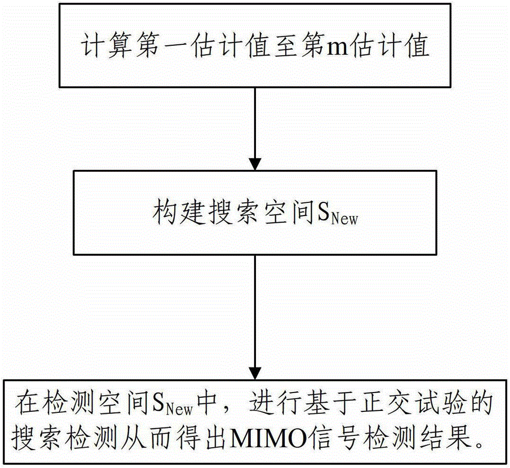
[0050] Such as figure 1 As shown, the MIMO signal detection method of this embodiment includes the following steps:

[0051] Step S1: Preliminarily detect the MIMO signal according to the preset method 1 to the preset method m, and obtain the first estimated value to the mth estimate in, m is an integer not less than 2, N is the number of antennas transmitting MIMO signals; MIMO signals are signals received by the MIMO system at a certain moment, a MIMO signal contains multiple inputs, and the number of inputs is equal to the number of antennas sent in the antenna matrix The number of antennas, MIMO signals are usually constructed as a vector containing elements equal to the number of antennas;

[0052] The first estimated value to the mth estimated value are all row vectors composed of N elements equal to the number of transmitting antennas in the antenna matrix; the value of m is obtained according to the requirements for computing performance and the computing power o...

Embodiment 2

[0062] In this embodiment, on the basis of the previous embodiment, the specific step S3 is as follows:

[0063] Step S3.1: According to S New The dimension m*n builds an orthogonal table L M (m n ); Wherein, what M represents is the number of times that needs the orthogonal test; The construction of orthogonal table is to select the orthogonal table that meets the requirements of this embodiment from the existing mature orthogonal table that has been built, and has the realization Simple and fast features;

[0064] E oq = Σ u = 1 M R u × W uoq Σ u = 1 ...

Embodiment 3

[0078] The MIMO signal detection method described in this embodiment is applied to the following system, which adopts 4-QAM modulation and a MIMO system with 3*3 antenna configuration. The signal sent by the sending end is: [-1+i, 1-i, -1+i], and the receiving end receives the signal r ^ = [ 5.23250 - 1.1947 i , - 2.6069 - 3.4946 i , - 4.5195 + 1.7132 i ]


PUM


Abstract

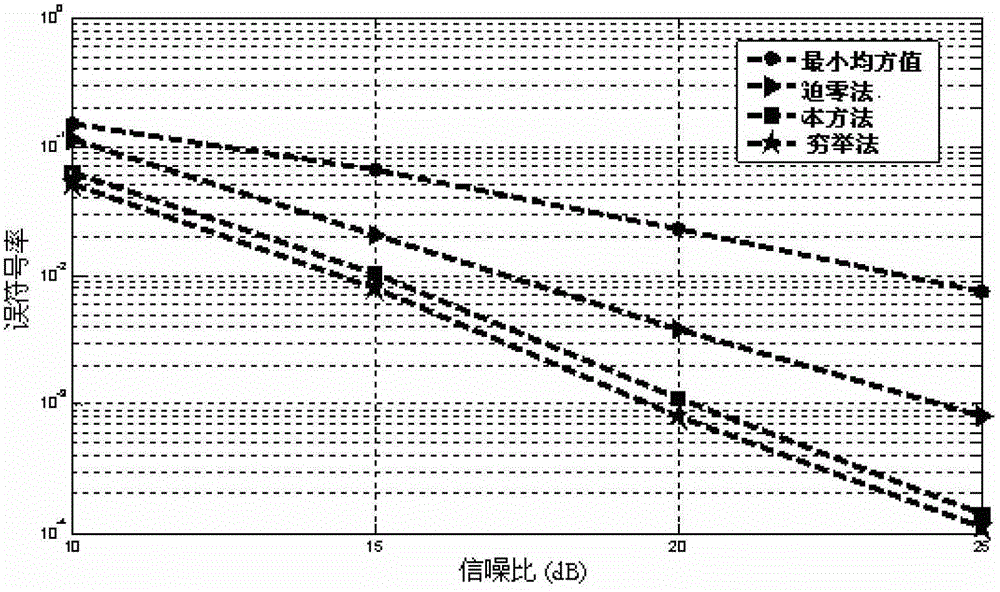
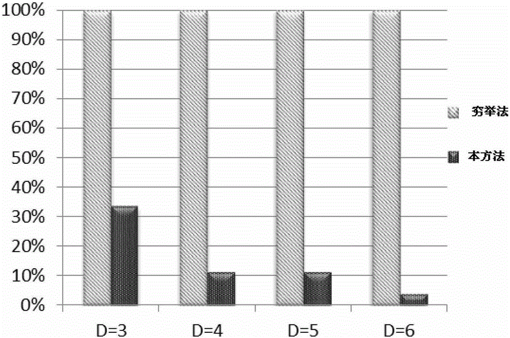
The invention discloses an MIMO signal detection method and device. The method comprises the following steps: step 1, preliminary detection is performed on MIMO signals according to methods from a first default method to an mth default method to obtain values from a first estimation value to an m estimation value, wherein m is an integer not smaller than 2, and N is equal to the number of antennas sending the MIMO signals; step 2, building a search spatial SNew according to the formula as follows: details in specification, wherein x1a=x2a=...=xma, and a is a positive integer not larger than N; and step 3, performing search detection based on an orthogonal experiment in the search spatial S<New> to draw an MIMO signal detection result. According to the detection result obtained by the MIMO signal detection method and device, compared with the traditional exhaustive search, the calculation complexity is reduced greatly under the condition that the decoding performance has no obvious loss.

Description

technical field [0001] The present invention relates to the communication field, in particular to a MIMO signal detection method and device. Background technique [0002] MIMO: Multiple-Input Multiple-Output, multiple input multiple output. [0003] The MIMO signal detection method involves the performance, complexity and practical application of MIMO system. At present, there are various signal detection methods and devices for MIMO signals, but there are the following problems: [0004] 1. Linear detection (such as zero-forcing ZF detector, minimum mean square error MMSE detector) and non-linear detection based on interference deletion (such as BLAST detector, divided into ZF-BLAST detector and MMSE-BLAST detector) are in error Poor performance in terms of code rate and signal-to-noise ratio; [0005] 2. Maximum likelihood (ML) detection, which searches all possible data spaces of the sending end at the receiving end, and obtains the value with the smallest distance fro...

Claims


Application Information

Patent Timeline
Patent Type & Authority Patents(China)
IPC IPC(8): H04B7/04H04B17/30H04B17/309
Inventor 崔琪楣
Owner WUXI BUPT SENSING TECH & IND ACADEMY
Learn More