Slot sliding key type simple self-locking inclined slide block pair device

A hole sliding key type, inclined slider technology, applied in the field of slotted hole sliding key type simple self-locking inclined slider pair device, can solve the problems of low efficiency, scrapped injection molding products, high cost, reduce cost, simplify structure, The effect of improving efficiency

Active Publication Date: 2013-08-21
NINGBO FANGZHENG TOOL
View PDF4 Cites 9 Cited by
  • Summary
  • Abstract
  • Description
  • Claims
  • Application Information

AI Technical Summary

Problems solved by technology

[0003] The oblique slider pair is driven by the oil cylinder to drive the active slider, and the driven slider carries the oblique core-pulling block, and the oblique core-pulling block is directly dragged by the oblique groove rail for oblique sliding or oblique resetting; the injection mold is in the During injection molding, due to the strong injection pressure, the inclined core block will be pushed through the inclined slider to make the piston rod of the oil cylinder retreat, resulting in the scrapping of the injection molded product; The self-locking oblique sliding block auxiliary device of the locking plane uses the self-locking plane to overcome the retraction of the oblique core-pulling block. For example, a kind of oblique sliding groove rail pair with a self-locking plane provided with the application number 201210436987.2, see Figure 5 , its complex structure is difficult to process, resulting in high cost, long processing period, and low efficiency. Therefore, the prior art has the problems and deficiencies of complex structure, high cost, and low efficiency

Method used


Image

  • Slot sliding key type simple self-locking inclined slide block pair device
  • Slot sliding key type simple self-locking inclined slide block pair device
  • Slot sliding key type simple self-locking inclined slide block pair device

Examples


Embodiment Construction

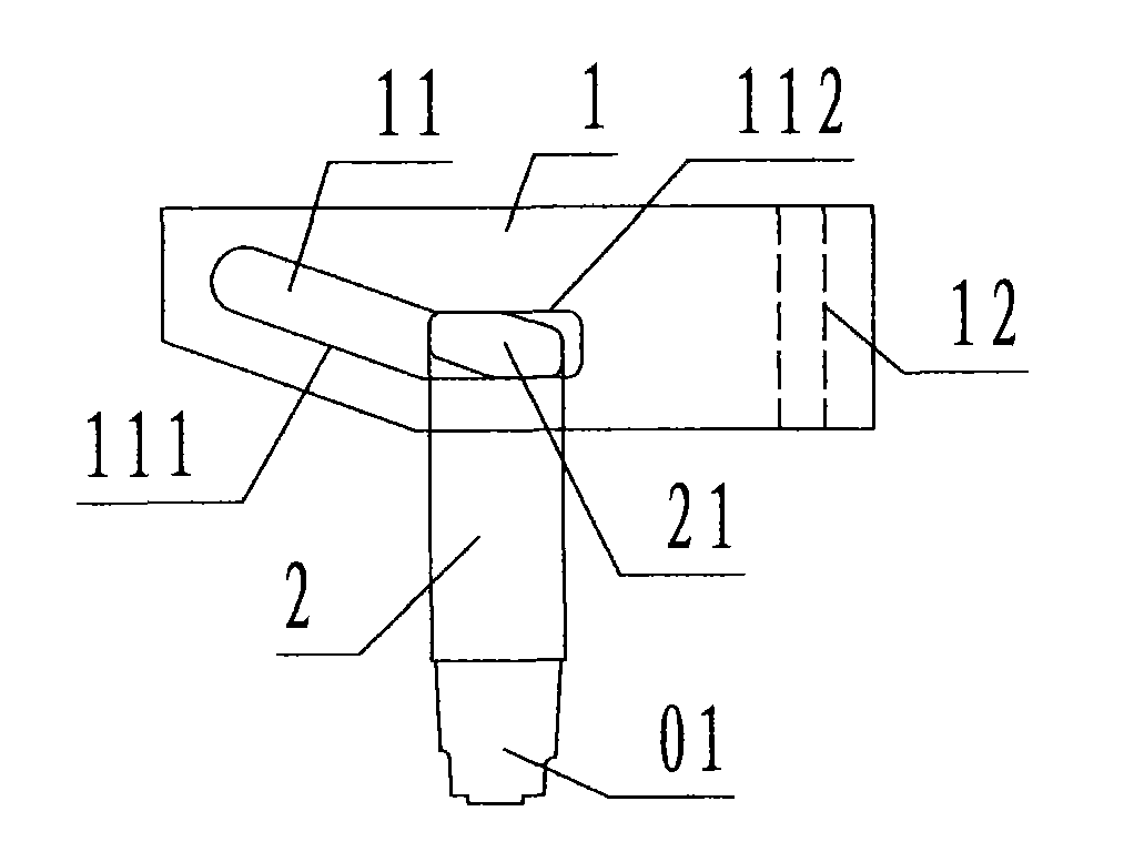
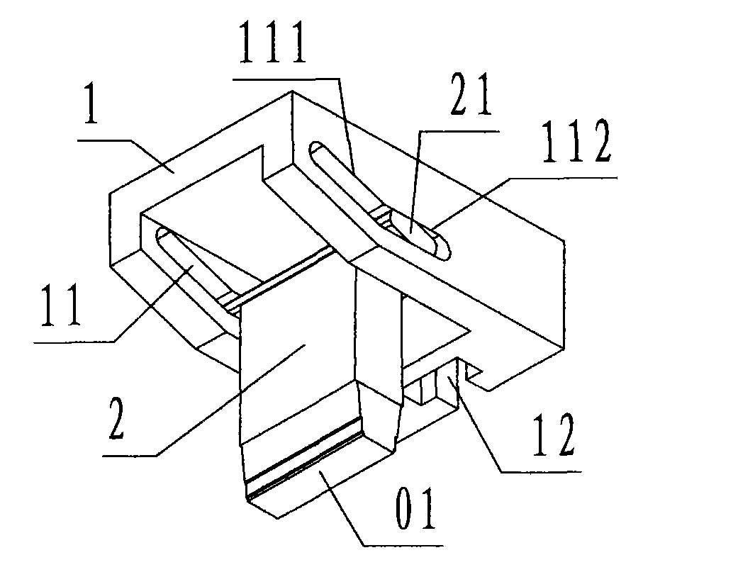
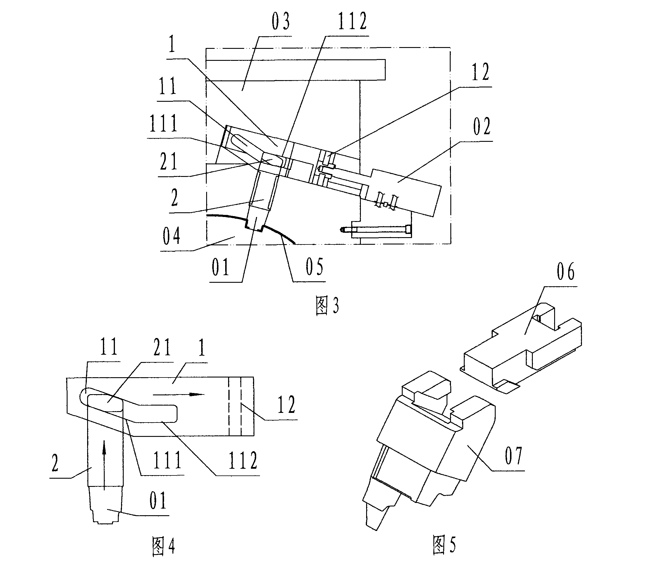
[0020] refer to Figure 1 to Figure 4 , a slotted key type simple self-locking oblique slider auxiliary device of the present invention, including a driving slider 1 and a driven slider 2, wherein: the driving slider 1 is a block steel formed by wedge-rectangular synthesis The material component, between the lower part of the left part of the active slider 1 and the left side of the active slider 1, there is a slope inclined to the left and upward called the wedge surface, and the lower part of the right part of the active slider 1 is the upper part of the active slider 1. Parallel planes are called straight planes; the bottom of the active slider 1 is provided with a groove with an open left end called a bottom groove, and the front and rear groove walls of the bottom groove are provided with folds parallel to the wedge surface and the straight plane. The curved and elongated through hole is called the chute hole 11. In the chute hole 11, the hole section corresponding to the...


PUM


Abstract

The invention discloses a slot sliding key type simple self-locking inclined slide block pair device which comprises a driving slide block (1) and a driven slide block (2). By adoption of the device consisting of the driving slide block and the driven slide block, when a sliding key is positioned at a straight sliding section, the stress motion direction of the driven slide block is orthogonal to the stress motion direction of the driving slide block; and during operation, the driving slide block straightly slides along the stress motion direction, an inclined sliding section of a chute hole of the driving slide block guides the sliding key to drive the driven slide block to move in an inclined manner, and when the sliding key slides into the straight sliding section, the problems and the defects of complex structure, high cost and low efficiency in the prior art are overcome by utilizing the technical scheme in which the stress motion direction of the driven slide block is orthogonal to the stress motion direction of the driving slide block and the driving slide block is prevented from retracting by locking the driven slide block through straight sliding, so that the aims of simplifying the structure, reducing the cost and improving the efficiency are fulfilled in the process of machining a self-locking inclined slide block pair.

Description

technical field [0001] The invention relates to an oblique slider device, in particular to a simple self-locking oblique slider sub-device of a slotted sliding key type used to drive an oblique core-pulling block for oblique extraction and demoulding in an injection mold. Background technique [0002] The oblique slider pair is a complete set of auxiliary devices that are used to drive the oblique core-pulling block inside the injection mold for oblique core-pulling demoulding by sliding and buckling the slider with the chute and the slider with the slide rail. [0003] The oblique slider pair is driven by the oil cylinder to drive the active slider, and the driven slider carries the oblique core-pulling block, and the oblique core-pulling block is directly dragged by the oblique groove rail for oblique sliding or oblique resetting; the injection mold is in the During injection molding, due to the strong injection pressure, the inclined core block will be pushed through the ...

Claims


Application Information

Patent Timeline
Patent Type & Authority Applications(China)
IPC IPC(8): B29C45/33B29C45/40
Inventor 文黎清俞君方刘璐金欢
Owner NINGBO FANGZHENG TOOL
Why Eureka
Try Eureka