
Device capable of rapidly hoisting large-section sliding form

A large segment, sliding form technology, applied in the field preparation of formwork/formwork/working frame, building components, construction, etc., to achieve the effect of easy sliding, increasing the height of one pouring, and reducing the frictional resistance of sliding form

Active Publication Date: 2015-02-25
CHINA RAILWAY NO 3 GRP CO LTD +1
View PDF4 Cites 0 Cited by
  • Summary
  • Abstract
  • Description
  • Claims
  • Application Information

AI Technical Summary

Problems solved by technology

[0004] In order to solve the problems existing in the existing sliding form, the present invention provides a fast-lifting large-segment sliding form device for cast-in-place concrete forming and construction construction projects

Method used


Image

  • Device capable of rapidly hoisting large-section sliding form
  • Device capable of rapidly hoisting large-section sliding form
  • Device capable of rapidly hoisting large-section sliding form

Examples


Embodiment Construction

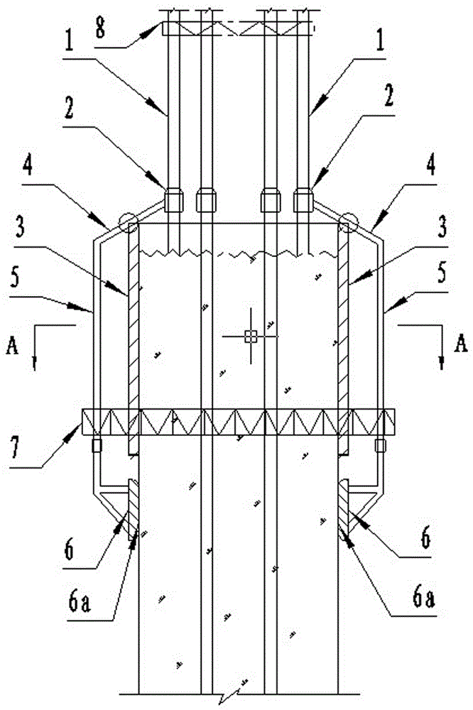
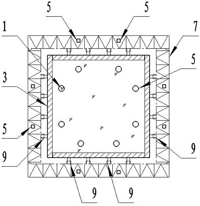
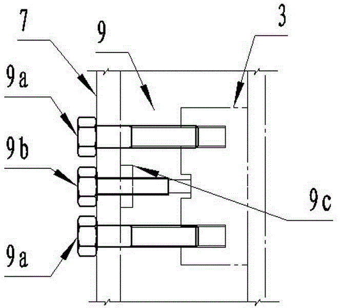
[0014] The rapid lifting large-segment sliding form device includes a formwork, a number of support rods 1, and sliding jacks 2 respectively set on each support rod 1. The formwork is composed of several unit formworks 3 that can be spliced ​​with each other to enclose a complete set of grooves. Each sliding jack 2 is fixedly connected with a diagonal rod 4, the diagonal rod 4 is at an angle to the support rod 1 where the sliding jack 2 is located, and the two sides of the top of each unit template 3 are respectively hinged on two diagonal rods In the middle part of 4, the other end of each oblique rod 4 is suspended and fixedly connected with a positioning rod 5, and the positioning rod 5 located at the lower part of each unit template 3 can be detachably connected with a sliding shoe plate 6, and the sliding shoe plate 6 and the positioning rod 5 The connection point is higher than the bottom end of the unit formwork 3, and the flat surface 6a on the sliding part of each shoe...


PUM


Abstract

The invention relates to building construction equipment, in particular to a device capable of rapidly hoisting a large-section sliding form in cast-in-place concrete forming construction engineering. The device capable of rapidly hoisting the large-section sliding form comprises a template, a plurality of bearing rods and hoisting jacks sleeved on the bearing rods. The template is formed by a plurality of unit templates forming a sleeve tank in an enclosing mode, each hoisting jack is fixedly connected with an inclined rod, an angle is formed between each inclined rod and the bearing rod where the corresponding hoisting jack is located, two sides of the top of each unit template are hinged to the middle portions of two inclined rods respectively, the other end of each inclined rod is fixedly connected with a positioning rod in a hanging mode, a sliding shoe plate is detachably connected with the positioning rod on the lower portions of the unit templates, and connecting points of the sliding shoe plates and the positioning rods are higher than bottoms of the unit templates. A flat face of each sliding shoe plate on a sliding portion and the inner side face of each unit template are located in the same gravity face. Each positioning rod in the middle portion of each unit template is respectively and fixedly provided with a Beilei frame composed of connecting rods.

Description

technical field [0001] The invention relates to building construction equipment, in particular to a fast-lifting large-segment sliding form device for cast-in-place concrete forming construction construction projects. Background technique [0002] Sliding form is a forming mold assembly mechanism used in cast-in-place concrete forming construction construction, mainly including formwork (including inner and outer formwork), formwork enclosure, and formwork door frame sliding mechanism. The template gantry sliding mechanism includes a lifting frame, a hanging hammer, a plurality of support rods 1, and sliding jacks 2 respectively sleeved on the support rods 1. The formwork is composed of several unit formworks 3, and the lift jacks 2 on each support rod 1 are jointly fixed on the lifting frame, the lower part of the lifting frame is fixed with a unit formwork enclosure, and the unit formwork enclosure is fixed with a unit Formwork 3, each unit formwork enclosure is welde...

Claims


Application Information

Patent Timeline
Patent Type & Authority Patents(China)
IPC IPC(8): E04G11/22
Inventor 周秋来于海霞陈俊杰余朋
Owner CHINA RAILWAY NO 3 GRP CO LTD
Learn More