Supercharge Your Innovation With Domain-Expert AI Agents!

Combustion liner guide stop and method for assembling a combustor

一种导向挡板、衬里挡板的技术,应用在燃烧方法、燃烧室、连续燃烧室等方向,能够解决昂贵维修费用、延长停机周期等问题

Inactive Publication Date: 2013-08-21
GENERAL ELECTRIC CO
View PDF10 Cites 0 Cited by
  • Summary
  • Abstract
  • Description
  • Claims
  • Application Information

AI Technical Summary

Problems solved by technology

The combustor liner and / or duct sleeve must be removed and workers must either machine the damaged part on-site or send the part off-site for repair, resulting in costly repairs and extended downtime

Method used


Image

  • Combustion liner guide stop and method for assembling a combustor
  • Combustion liner guide stop and method for assembling a combustor
  • Combustion liner guide stop and method for assembling a combustor

Examples


Embodiment Construction

[0018] Reference will now be made in detail to various embodiments of the invention, one or more examples of which are illustrated in the drawings. Each example is provided by way of explanation of the invention, not limitation of the invention. In fact, those skilled in the art will readily appreciate that various modifications and variations can be made in the present invention without departing from the scope or spirit of the invention. For example, features illustrated or described as part of one embodiment can be used on another embodiment to yield a still further embodiment. Thus, it is intended that the present invention covers such modifications and changes as come within the scope of the appended claims and their equivalents.

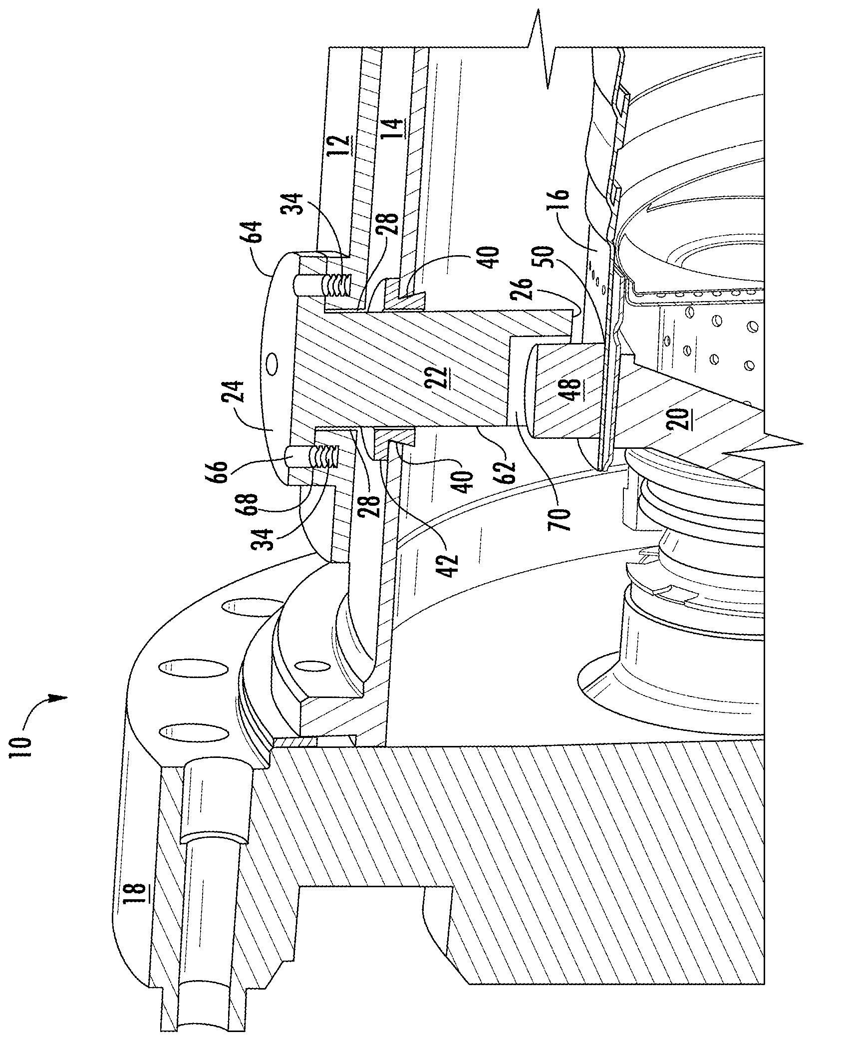
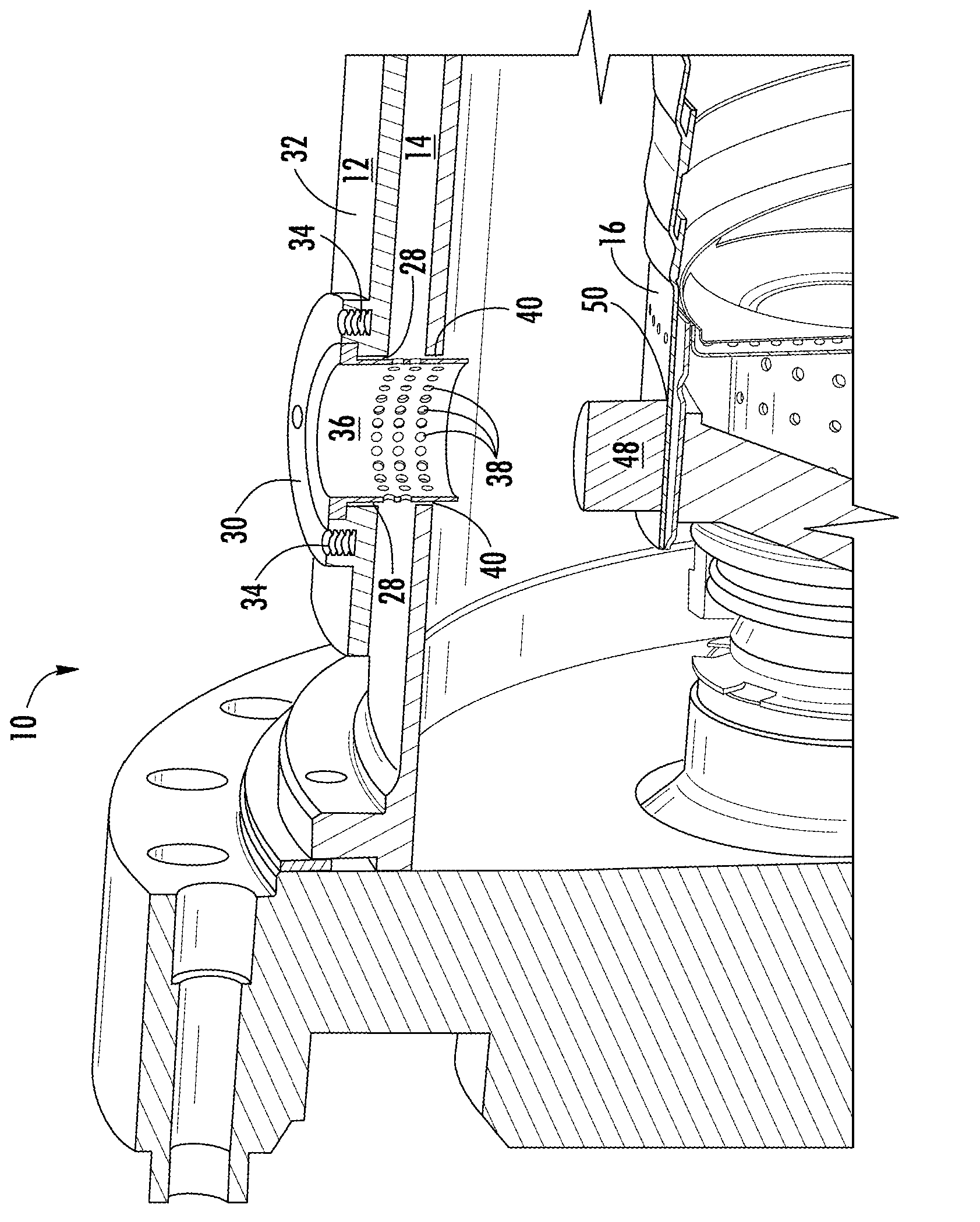
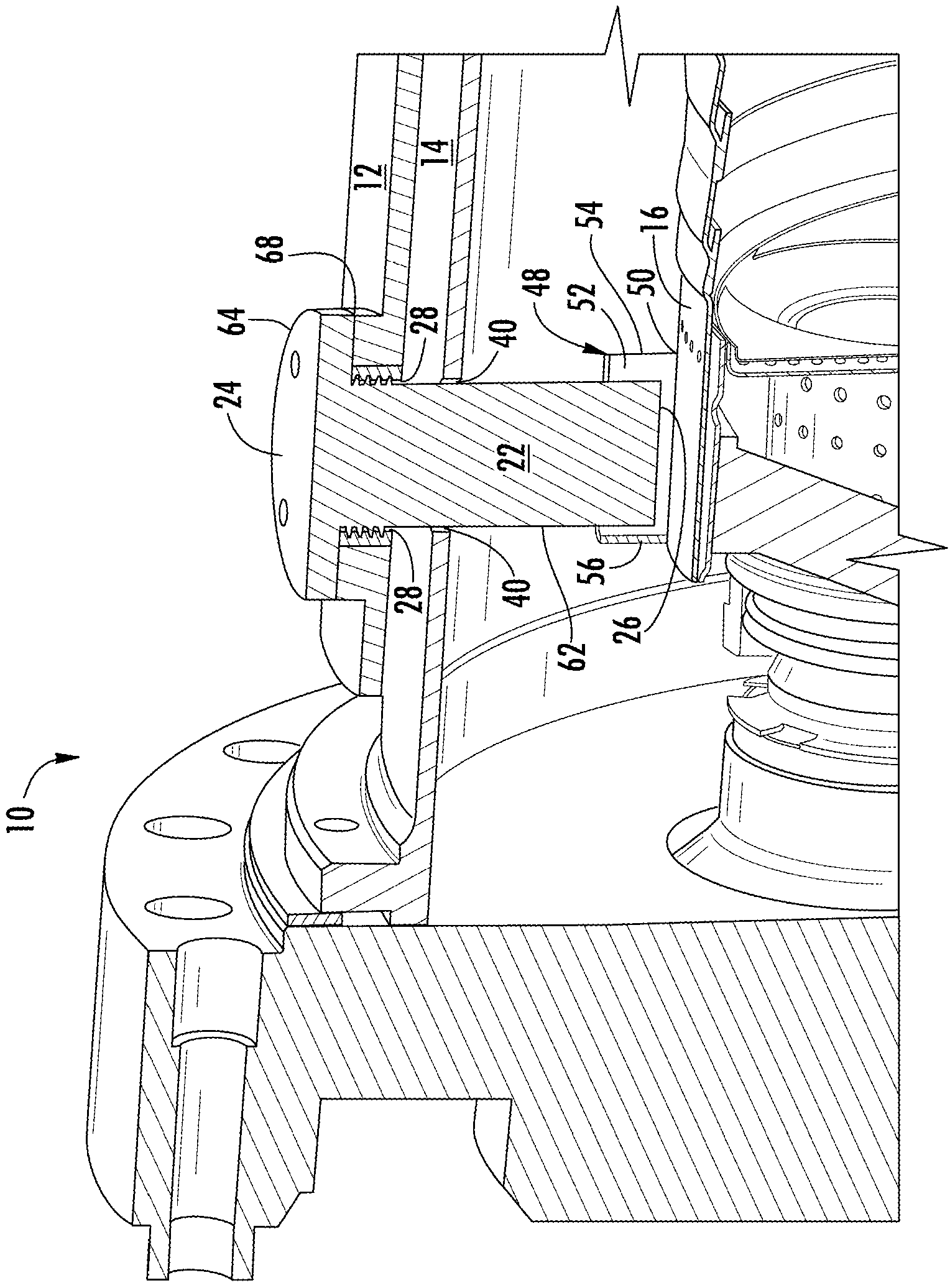
[0019] The present invention generally relates to a gas turbine combustor including a casing, a flow sleeve, a combustor liner, and a liner guide baffle. The invention also relates to a method for assembling a burner. In various embodiments,...


PUM


Abstract

A combustor for a gas turbine including a casing, a flow sleeve at least partially disposed within the casing, a combustion liner at least partially disposed within the flow sleeve, a liner stop feature extending from the combustion liner, and a liner guide stop including a first end separated from a second end, the second end configured to be at least partially engaged with the liner stop feature, wherein the liner guide stop extends through the casing and the flow sleeve.

Description

technical field [0001] The present invention relates generally to combustor liner guide baffles for gas turbine combustors, and more particularly to combustion liner guide baffles inserted through combustor casings and methods for assembling said combustors. Background technique [0002] A gas turbine generally includes a compressor section, a combustor section, and a turbine section. The compressor section pressurizes the air flowing into the turbine. Pressurized air discharged from the compressor section flows into the combustor section, which is typically characterized by a plurality of combustors arranged in an annular array about the axis of the gas turbine. Each of the plurality of combustors includes a combustor liner that defines a combustor's combustion chamber. Thus, the air entering each combustor is mixed with fuel and burned within the combustion chamber lining. Hot combustion gases flow from the combustor liner through the transition piece into the turbine s...

Claims


Application Information

Patent Timeline
Patent Type & Authority Applications(China)
IPC IPC(8): F23R3/00
CPCF23R3/002F23R3/60F23R2900/00017Y10T29/49231
Inventor A.P.德赛P.K.蒂瓦里
Owner GENERAL ELECTRIC CO
Features
  • R&D
  • Intellectual Property
  • Life Sciences
  • Materials
  • Tech Scout
  • Unparalleled Data Quality
  • Higher Quality Content
  • 60% Fewer Hallucinations
Learn More