A method and system for automatic testing of electric vehicle charging facilities
An automatic test system and charging facility technology, applied in the direction of measuring electricity, measuring devices, measuring electrical variables, etc., can solve problems such as low efficiency, incomplete functions, and uneven performance parameters of charging facilities, achieving high integration and small size , easy maintenance and calibration effect
- Summary
- Abstract
- Description
- Claims
- Application Information
AI Technical Summary
Problems solved by technology
Method used
Image
Examples
Embodiment 1
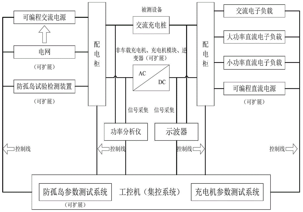
[0057] figure 1 It is a block diagram of the overall structure of the automatic test system for electric vehicle charging facilities of the present invention.
[0058] The input terminal of the test system: adopts programmable AC power supply, mainly to provide standard AC power supply, which can change the output of different voltages and frequencies, and program the output of abnormal conditions of the power grid, including phase difference, voltage difference, harmonic influence, voltage Various factors such as sudden rise and sudden drop, assess the adaptability of AC charging piles and off-board chargers to unstable power grids and the stable output capability of signals, and also measure the parameters of the AC power supply at the input end, including voltage, current, and power Wait. In addition, the input end can be equipped with an anti-islanding test detection device for detection of photovoltaic grid-connected inverters.
[0059] The output part of the test syste...
Embodiment 2
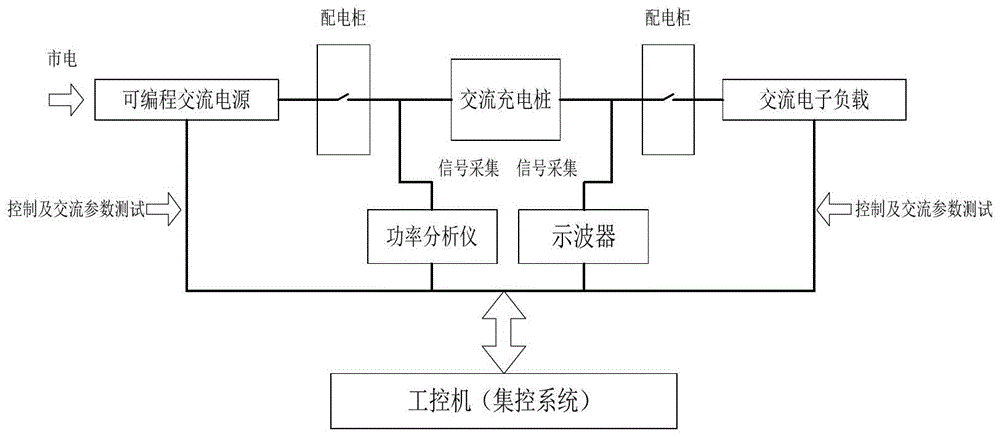
[0063] figure 2 Schematic diagram of the system tested for the AC charging pile.
[0064] 1. Connect the AC charging pile to be tested to the testing platform;
[0065] 2. Set the programmable AC power supply and AC electronic load parameters according to the test items, respectively for the AC input characteristics of the AC charging pile (harmonic current, surge current, input power, power factor and efficiency, voltage interruption, voltage fluctuation, voltage sudden Rise / sag, frequency change, etc.), control pilot signal (output voltage, PWM frequency, rise / fall time, etc.), protection function characteristics (including on-load switching circuit, short circuit protection, overcurrent protection, etc.), insulation resistance and leakage current test;
[0066] 3. The centralized control system collects the relevant data tested by the equipment by communicating with the programmable AC power supply, AC electronic load, power analyzer and oscilloscope;
[0067] 4. Analyz...
Embodiment 3
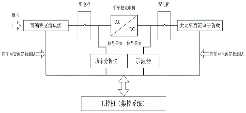
[0070] image 3 Schematic of the system tested for the off-board charger.
[0071] 1. Connect the non-vehicle charger to be tested to the testing platform;
[0072] 2. Set the parameters of programmable AC power supply and high-power DC electronic load according to the test items, respectively for AC input characteristics (inrush current, input power, power factor and efficiency, etc.), DC output characteristics (output voltage error, voltage regulation accuracy, Output current error, steady current accuracy, ripple coefficient, current sharing unbalance, etc.), communication protocol (charger and BMS communication, CAN Bus read / write), protection function characteristics (soft start, abnormal connection status, power-off restart , input overvoltage / undervoltage protection, anti-output short-circuit function, anti-battery reverse connection function, current limiting / voltage limiting function), insulation resistance and leakage current, etc.;
[0073] 3. The centralized cont...
PUM
 Abstract
Description
Claims
Application Information
 - R&D
- Intellectual Property
- Life Sciences
- Materials
- Tech Scout
- Unparalleled Data Quality
- Higher Quality Content
- 60% Fewer Hallucinations
Browse by: Latest US Patents, China's latest patents, Technical Efficacy Thesaurus, Application Domain, Technology Topic, Popular Technical Reports.
© 2025 PatSnap. All rights reserved.Legal|Privacy policy|Modern Slavery Act Transparency Statement|Sitemap|About US| Contact US: help@patsnap.com


