
Eureka
For R&D, Eureka makes reading and utilizing patents & technical documents easy.
Eureka AIR
Designed for self-driven R&D workflows. Generate viable solutions, solve complex R&D challenges, empower your innovation with AI.

Eureka Materials
Designed for material experts only. Revolutionize your material R&D, from search, analyze, to developing new materials.

TechResearch
Generate reliable direction feasibility study reports for your R&D in just a few steps.

TechSeek
Discover and master advanced knowledge NOW. Basics, ideas, possibilities, all at once.

TechMind
As an expert in R&D Theories, TechMind can generates customized viable solutions instantly.

TechRisk
Analyze your overall solution with one click, know your potential R&D risks in advance.

TechMonitor
Get weekly tech updates, stay abreast of the latest tech innovations and key insights.
Solar cell module and manufacturing method thereof
A solar cell and manufacturing method technology, applied in circuits, electrical components, photovoltaic power generation, etc., can solve the problems of poor thermal expansion, increased manufacturing costs, warping and damage of solar cell components, and achieve the effect of small warpage
- Summary
- Abstract
- Description
- Claims
- Application Information
AI Technical Summary
Problems solved by technology
Method used
Image

Examples
Embodiment approach 1
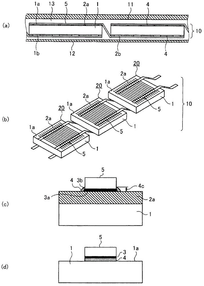
[0027] figure 1 is a diagram showing the structure of a solar cell module according to Embodiment 1 of the present invention, figure 1 (a) is a cross-sectional view of the solar cell module, figure 1 (b) is a perspective view of a series group in which a plurality of solar cell elements 1 are connected by a wiring member 5 , figure 1 (c) is a cross-sectional view of the joint portion of the thin wire electrode (first collector electrode) 2 a and the wiring member 5 , figure 1 (d) is a cross-sectional view showing a junction between the light receiving surface 1 a and the wiring member 5 .
[0028] according to figure 1 (a), the solar battery module 100 is provided with a light-receiving surface protection member 11 on the light-receiving surface 1 a side of the solar battery series group 10 , and a rear surface protection member 12 is arranged on the back surface 1 b side, and between the solar battery series group 10 and the protection members 11 and 12 The sealing member...
Embodiment approach 2
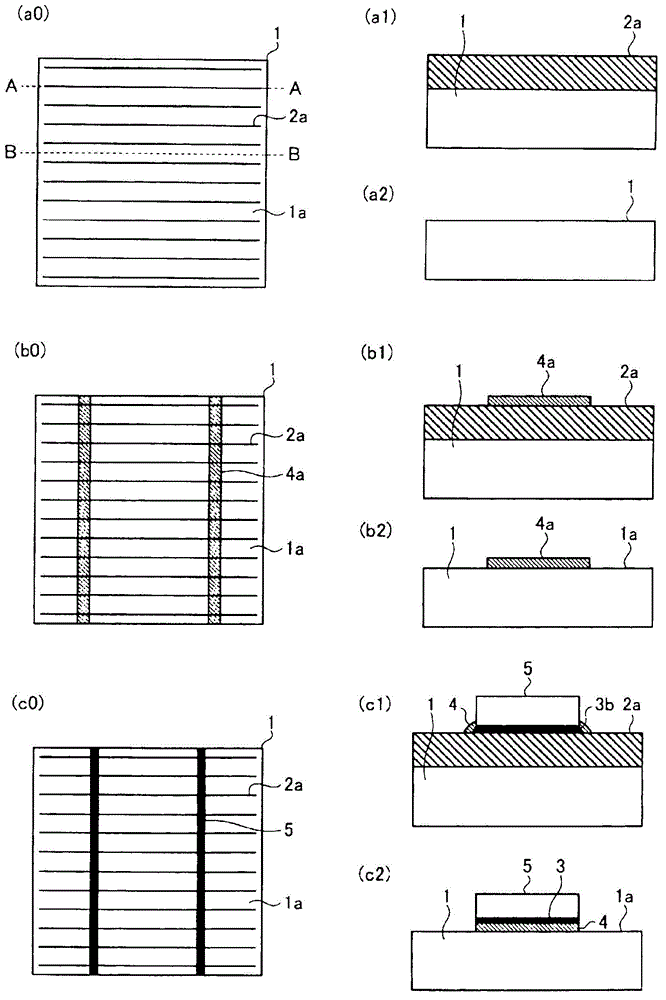
[0039] figure 2 It is a figure which shows the solar cell module of Embodiment 2 of this invention, and is for demonstrating the method of bonding the solar cell element 1 and the wiring member 5 in order. figure 2 ( a0 ) is a plan view of the light receiving surface 1 a of the solar cell element 1 . A plurality of thin wire electrodes 2a are formed in parallel on the light receiving surface 1a. figure 2 (a1) is figure 2 The cross-sectional view along line AA of ( a0 ) shows a cross-section of the thin wire electrode 2 a in a direction intersecting the wiring member 5 . figure 2 (a2) is figure 2 The cross-sectional view along line BB of ( a0 ) shows the cross-section of the region other than the thin wire electrode 2 a.
[0040] figure 2 (b0) is a plan view of the light-receiving surface 1a in a state where the thermosetting epoxy resin composition 4a before curing is arranged, and the above-mentioned thermosetting epoxy resin composition 4a contains an organic aci...
Embodiment approach 3
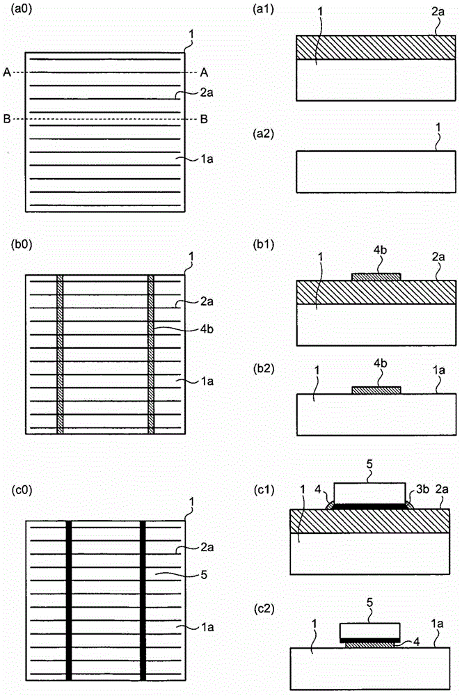
[0048] image 3 It is a figure which shows the solar cell module of Embodiment 3 of this invention, and is used for demonstrating the bonding method of the solar cell element 1 and the wiring member 5. image 3 (a0) is a figure for demonstrating the method of joining the wiring member 5 of the solar cell element 1. image 3 (a1) is image 3 (a0) A cross-sectional view corresponding to the line A-A. image 3 (a2) is image 3 (a0) Cross-sectional view corresponding to line BB. A plurality of thin wire electrodes 2a are formed in parallel on the light receiving surface 1a of the solar cell element 1 .
[0049] image 3 (b0) is a diagram showing the state where the thermosetting epoxy resin composition 4b before curing is arranged. The thermosetting epoxy resin composition 4b is narrower than the width of the wiring member 5 and contains an organic acid or Organic acids are used in hardeners. image 3 (b1) is image 3 (b0) A cross-sectional view corresponding to the line A...
PUM
 Abstract
Description
Claims
Application Information
 - R&D Engineer
- R&D Manager
- IP Professional
- Industry Leading Data Capabilities
- Powerful AI technology
- Patent DNA Extraction
Browse by: Latest US Patents, China's latest patents, Technical Efficacy Thesaurus, Application Domain, Technology Topic, Popular Technical Reports.
© 2024 PatSnap. All rights reserved.Legal|Privacy policy|Modern Slavery Act Transparency Statement|Sitemap|About US| Contact US: help@patsnap.com