a coding machine

A coding machine and machine body technology, applied in printing devices, printing, etc., can solve the problem of waste of printing tape width, achieve the effect of saving printing cost and improving utilization rate

Active Publication Date: 2015-09-30
苏州江天包装科技股份有限公司
View PDF7 Cites 0 Cited by
  • Summary
  • Abstract
  • Description
  • Claims
  • Application Information

AI Technical Summary

Problems solved by technology

[0002] such as As shown in Figure 3, an existing coding machine, a coding machine, includes a fuselage, a printing device fixed on the side of the fuselage, a paper tape shaft, a printing tape shaft, a guide roller, a rotating The printing tape collection roller arranged on the side of the fuselage, the paper tape and printing tape enter from one side of the printing device, and after coming out, they are guided into the printing tape collection roller through the introduction roller. Since it is a coding machine, the printing tape printed on the paper tape Only partially, more width on the printing tape is wasted

Method used


Image

  • a coding machine
  • a coding machine
  • a coding machine

Examples


Embodiment 1

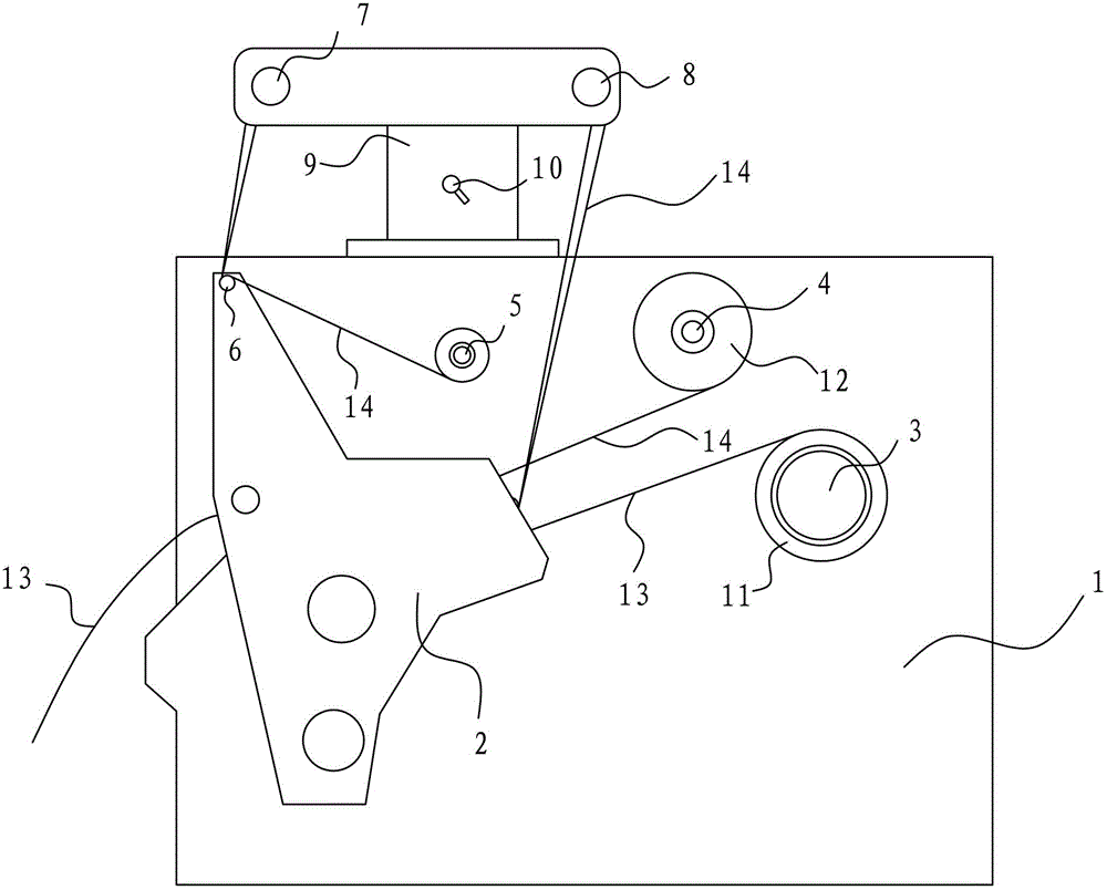
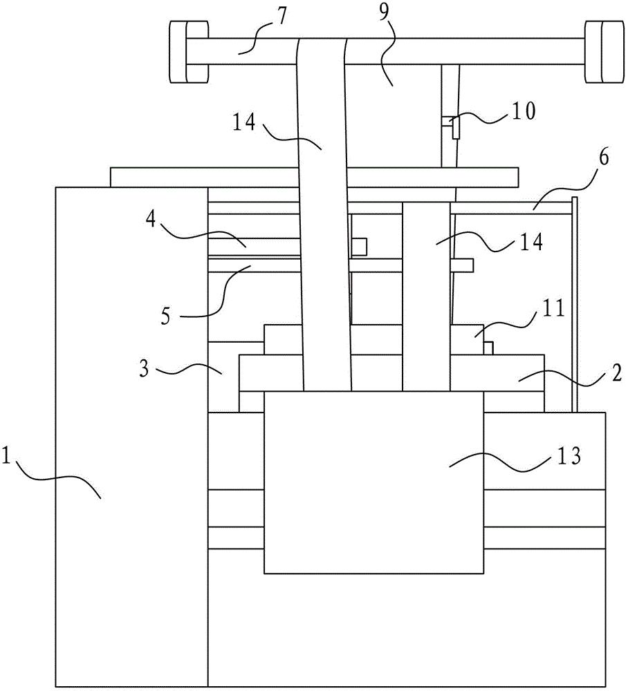
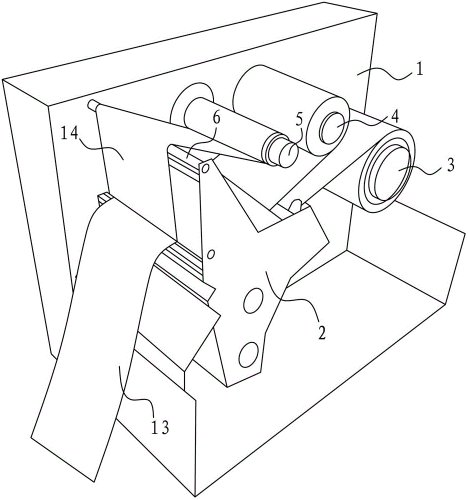
[0014] Embodiment one: see attached Figure 1-2 As shown, a coding machine includes a fuselage 1, a printing device 2 fixed on the side of the fuselage, a paper tape shaft 3, a printing tape shaft 4, a first guide roller 6, and a rotating device arranged on the side of the fuselage The printing tape collection roller 5, the paper tape shaft 3, the printing tape shaft 4, the first guide roller 6, and the printing tape collection roller 5 are parallel to each other, the paper tape shaft 3 is provided with a paper tape roll 11, and the printing tape A printing tape roll 12 is arranged on the shaft 4, a paper tape 13 and a printing tape 14 enter from one side of the printing device 2, and a second guide roller 7 and a third guide roller 8 are arranged above the fuselage 1. The second guide roller 7 and the third guide roller 8 are rotatably arranged on the guide seat 9, and the guide seat 9 is rotatably arranged on the top of the fuselage 4, and the printing belt 14 passes throu...


PUM


Abstract

The invention discloses a coding machine which comprises a machine body, a printing device fixed on one side of the machine body, a paper tape spool, a printing tape spool, a first guiding roller, and a printing tape collecting roller arranged on one side of the machine body in a rotary mode, wherein a second guiding roller and a third guiding roller are further arranged above the machine body, the second guiding roller and the third guiding roller are arranged on a guiding base in a rotary mode, and the guiding base is arranged on the machine body in a rotary mode. Due to the fact that a narrow printing tape is adopted and can be reused, the using rate of the printing tape is improved on the premise that printing quality is not affected, and printing cost is saved.

Description

technical field [0001] The invention relates to the field of printing machinery, in particular to a coding machine. Background technique [0002] like image 3 As shown, there is an existing coding machine, a coding machine, which includes a fuselage, a printing device fixed on the side of the fuselage, a paper tape shaft, a printing tape shaft, a guide roller, and a rotating device mounted on the fuselage. The printing tape collection roller on the side, the paper tape and printing tape enter from one side of the printing device, and after coming out, they are guided into the printing tape collecting roller through the introduction roller. Most of the width is wasted. Contents of the invention [0003] The purpose of the present invention is to provide a coding machine with a higher utilization rate of the printing tape. [0004] In order to achieve the above object, the technical solution adopted by the present invention is: a coding machine, which includes a fuselage,...

Claims


Application Information

Patent Timeline
Patent Type & Authority Patents(China)
IPC IPC(8): B41J15/00
Inventor 唐德勇朱文斌
Owner 苏州江天包装科技股份有限公司
Why Eureka
Try Eureka