Supercharge Your Innovation With Domain-Expert AI Agents!

Device for realizing vertical lifting by using film-grade laminator flow

A membrane-level, airflow-direction technology, applied in jet flaps and other directions, can solve problems such as high fuel consumption, poor rotor aerodynamic performance, and low efficiency in the vertical take-off process, achieving the effect of saving fuel

Active Publication Date: 2013-08-28
李治国
View PDF5 Cites 0 Cited by
  • Summary
  • Abstract
  • Description
  • Claims
  • Application Information

AI Technical Summary

Problems solved by technology

The rotor has poor aerodynamic performance and high fuel consumption, so its range is short
[0006] 3. Rely on downward jet to obtain lift. For example, Harrier type aircraft can only obtain 4N lift per kilowatt of kinetic energy, and the efficiency of vertical take-off process is low, only 22% of roll take-off

Method used


Image

  • Device for realizing vertical lifting by using film-grade laminator flow
  • Device for realizing vertical lifting by using film-grade laminator flow
  • Device for realizing vertical lifting by using film-grade laminator flow

Examples


Embodiment Construction

[0027] The present invention will be described in further detail below in conjunction with the accompanying drawings and specific embodiments.

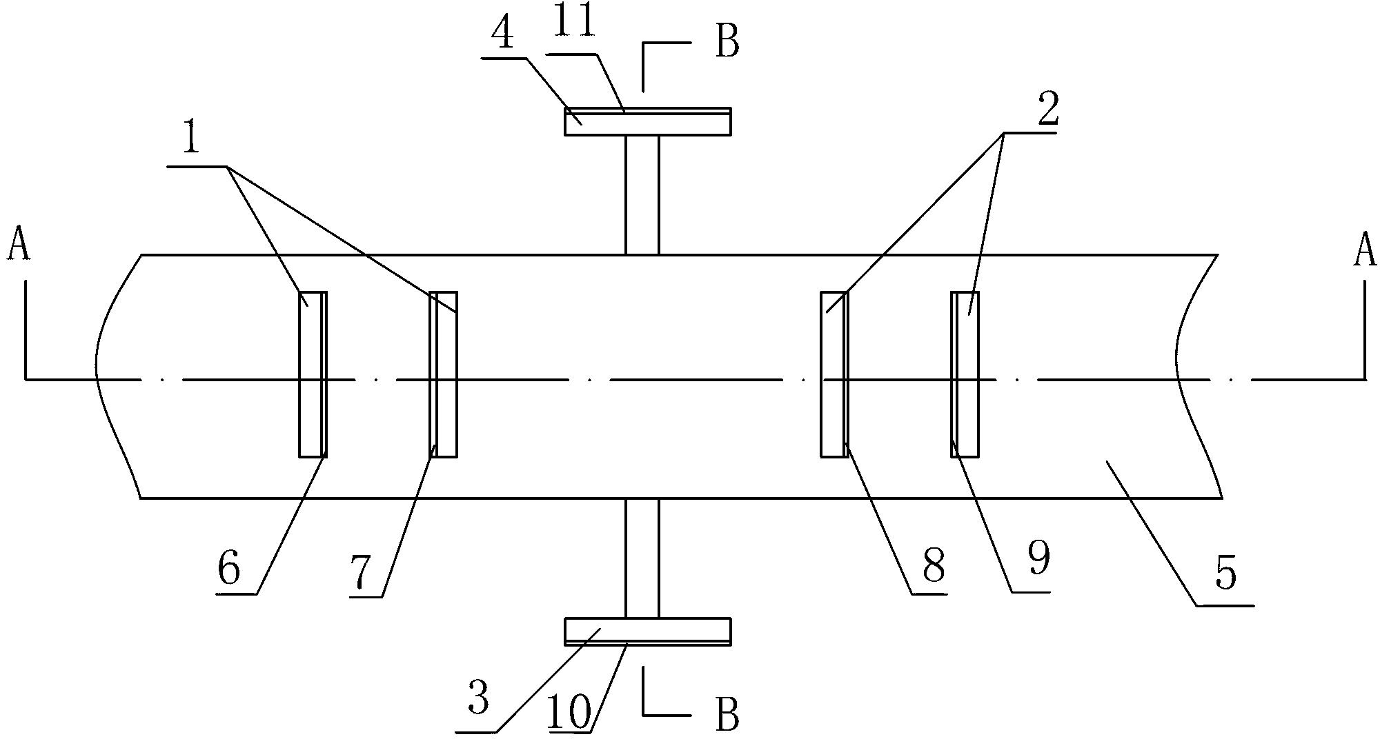
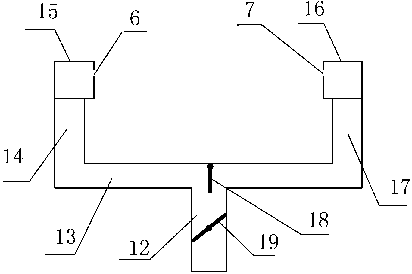
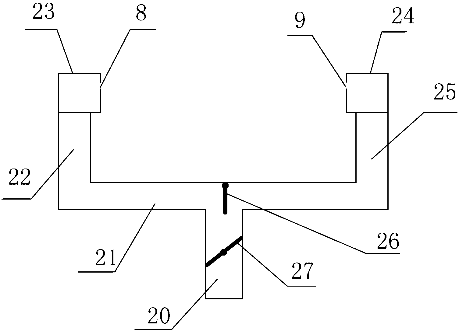
[0028] The present invention utilizes the schematic diagram of the device of film-level laminar flow to realize direct lift as Figure 1-Figure 5 As shown, it includes a gas source, a gas transmission main pipe, and a slit A unit 1, a slit B unit 2, a slit C unit 3 and a slit D unit 4. One end of the gas transmission main pipe is sealed, and the other end is connected to the The air source connection, the air source can be a turbojet engine, or a turbofan engine, or a combination of other types of engines and axial fans or centrifugal fans. The slit A unit 1 is composed of two first slits 6 and second slits 7 with opposite airflow directions and an airflow direction control valve A18 controlling the airflow direction of the slit A unit. The first slit 6 Between the second narrow slit 7 is a zone A of laminar flow straight up. The sl...


PUM


Abstract

The invention discloses a device for realizing vertical lifting by using a film-grade laminator flow. The device comprises an air source, an air transportation main pipeline, a narrow slit A unit, a narrow slit B unit, a narrow slit C unit and a narrow slit D unit, wherein a laminator flow vertical-lifting A region is arranged between a first narrow slit and a second narrow slit, a laminator flow vertical-lifting B region is arranged between a third narrow slit and a fourth narrow slit, the first narrow slit, the second narrow slit, the third narrow slit and the fourth narrow slit are in the same plane and are all 2-5mm wide, the narrow slit A unit and the narrow slit B unit are respectively positioned at the top of a device to be vertically lifted, and air is sprayed along the head-tail direction of the device to be vertically lifted. The narrow slit C unit and the narrow slit D unit are respectively positioned at twos sides of the device to be vertically lifted, a fifth narrow slit is arranged on the narrow slit C unit, a sixth narrow slit is arranged on the narrow slit D unit, and the fifth narrow slit and the sixth narrow slit spray air in a direction vertical to the outside of the device to be vertically lifted. According to the device, the air is sprayed through the narrow slits to form the film-grade laminar flow, and a vertical lifting force is provided for an object needing to be vertically lifted.

Description

technical field [0001] The invention relates to the technical field of fluid mechanics, in particular to a device for realizing direct lift by using membrane-level laminar flow. Background technique [0002] With the advancement of science and technology, various aircrafts have developed rapidly. [0003] At present, there are three main ways for various types of aircraft to obtain lift: [0004] 1. The fixed wing moves in a straight line in the atmosphere to obtain lift, such as Boeing 747, Airbus A320, etc. The lift of this type of aircraft depends on the runway, and it can only travel between large airports. paralysis. [0005] 2. The rotor rotates in the atmosphere to obtain lift, such as helicopters. The rotor has poor aerodynamic performance and high fuel consumption, so its range is short. [0006] 3. Rely on the downward jet to obtain lift. For example, the Harrier can only obtain 4N lift per kilowatt of kinetic energy, and the efficiency of the vertical take-off...

Claims


Application Information

Patent Timeline
IPC IPC(8): B64C9/38
Inventor 李治国
Owner 李治国
Features
  • R&D
  • Intellectual Property
  • Life Sciences
  • Materials
  • Tech Scout
  • Unparalleled Data Quality
  • Higher Quality Content
  • 60% Fewer Hallucinations
Learn More