
Anti-misoperation demarcating load switch with disconnecting link

A technology of load switch and knife switch, applied in the field of anti-misoperation demarcation load switch, can solve the problems of safety hazards, hidden dangers, loose connection safety, etc., and achieve the effect of strong opening and closing ability, compact structure and good safety performance.

Inactive Publication Date: 2013-08-28
周文伟
View PDF4 Cites 0 Cited by
  • Summary
  • Abstract
  • Description
  • Claims
  • Application Information

AI Technical Summary

Problems solved by technology

The existing boundary load switch does not have the function of isolating the knife switch for grounding. When the fault area is determined on the line and the power maintenance work is started, the usual practice is to disconnect the load switch first, then pull the isolating switch, and connect the working grounding wire behind it. The maintenance work can be started. Since the current overhead distribution lines are mainly insulated wires, and the T-connection of the user is generally an insulated wire or a high-voltage cable T-connection, it is impossible to connect the ground wire without destroying the insulation layer of the wire, and there is a great potential safety hazard.
In order to avoid safety accidents, electric workers usually add special grounding rings or hanging grounding wires at the connection between T-contact wires and wires, and wires and cables. security risks

Method used


Image

  • Anti-misoperation demarcating load switch with disconnecting link
  • Anti-misoperation demarcating load switch with disconnecting link

Examples


Embodiment Construction

[0009] Below in conjunction with accompanying drawing and specific embodiment the present invention is described in further detail:

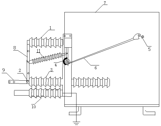
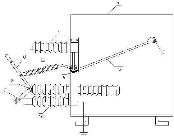
[0010] Such as figure 1 As shown, a kind of anti-misoperation demarcation load switch with a knife switch includes a demarcation load switch, a locking tooth 5 and a locking lever 6 are arranged in the housing 7 of the demarcation load switch, and the housing 7 of the demarcation load switch There is a three-station isolation knife switch on the incoming line side. The three-station isolation knife switch includes a knife switch, a static contact 1, a moving contact 2, a grounding static contact 10, and a knife drive shaft 4. The static contact 1 is connected to the upper incoming line board of the boundary load switch, the moving contact 2 is connected to the incoming line board 3, the grounding static contact 10 is connected to the bottom of the incoming line side of the shell, and the main knife switch 8 and the grounding knife switch 9 are p...


PUM


Abstract

The invention discloses an anti-misoperation demarcating load switch with a disconnecting link. The anti-misoperation demarcating load switch with the disconnecting link comprises a demarcating load switch. A clamping tooth (5) and a locking rod (6) are arranged in the shell (7) of the demarcating load switch; a three-position separation disconnecting link is arranged on the line inlet side of the shell (7) of the demarcating load switch, and comprises a disconnecting link body, a fixed contact (1), a moving contact (2), an grounded fixed contact (10) and a disconnecting link transmission shaft (4). A crank connecting rod (11) is connected to the disconnecting link transmission shaft (4); the crank end of the crank connecting rod (11) is connected to the disconnecting link transmission shaft (4), and the connecting end of the crank connecting rod (11) is hinged in the middle of a main disconnecting link (8); the locking rod (6) is connected to the disconnecting link transmission shaft (4), and rotates along with the disconnecting link transmission shaft (4); the far end of the locking rod (6) makes contact with or is separated from the clamping tooth (5) in the shell of the demarcating load switch. The demarcating load switch is time-saving, labor-saving, safe and convenient to operate.

Description

technical field [0001] The invention relates to a boundary load switch, in particular to an anti-misoperation boundary load switch with a knife switch. Background technique [0002] The boundary load switch is a kind of responsibility demarcation point installed on 10KV overhead distribution lines, which can automatically cut off and isolate lines with single-phase ground faults and phase-to-phase short-circuit faults. The existing boundary load switch does not have the function of isolating the knife switch for grounding. When the fault area is determined on the line and the power maintenance work is started, the usual practice is to disconnect the load switch first, then pull the isolating switch, and connect the working grounding wire behind it. The maintenance work can be started. Since the current overhead distribution lines are mainly insulated wires, and the T-connection of the user is generally an insulated wire or a high-voltage cable T-connection, it is impossible ...

Claims


Application Information

Patent Timeline
Patent Type & Authority Applications(China)
IPC IPC(8): H01H31/04
Inventor 周文伟付敏
Owner 周文伟
Learn More