Tubular product hydraulic forming device capable of achieving inside and outside pressurization

A hydroforming and pipe technology, applied in the field of pipe hydroforming, can solve the problem of simultaneous loading of pipes

Active Publication Date: 2015-04-08
HARBIN INST OF TECH
View PDF7 Cites 2 Cited by
  • Summary
  • Abstract
  • Description
  • Claims
  • Application Information

AI Technical Summary

Problems solved by technology

[0007] Aiming at the problem that conventional internal high-pressure forming dies cannot realize the simultaneous loading of internal and external pressure and axial feeding of pipes, the present invention proposes a pipe hydroforming device that can realize internal and external pressure

Method used


Image

  • Tubular product hydraulic forming device capable of achieving inside and outside pressurization
  • Tubular product hydraulic forming device capable of achieving inside and outside pressurization
  • Tubular product hydraulic forming device capable of achieving inside and outside pressurization

Examples


specific Embodiment approach 1

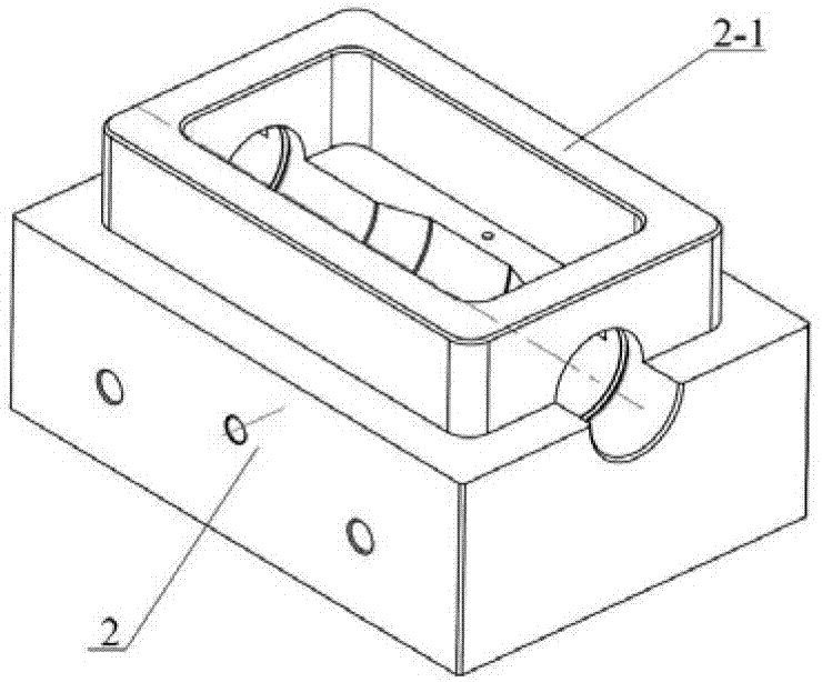
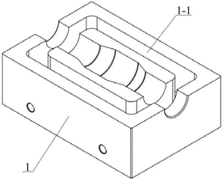
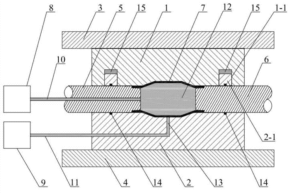
[0036] Embodiment 1: Combining Figure 1 to Figure 10This embodiment is described. In this embodiment, a pipe hydroforming device that can realize internal and external pressure includes a die upper die 1, a die lower die 2, an upper die plate 3, a lower die plate 4, a left punch 5, a right punch Head 6, the mold upper mold 1 and the mold lower mold 2 are closed to form a complete mold cavity, which is located between the upper mold plate 3 and the lower mold plate 4, the upper mold plate 3 is connected to the mold upper mold 1, and the lower mold plate 4 is connected to the mold lower mold. 2 connections. The two ends of the mold cavity are respectively provided with a left punch 5 and a right punch 6; the left punch 5 is provided with a first liquid channel 10 along its axial direction, and the internal pressure booster 8 passes through the first liquid channel 10 is communicated with the inner cavity of the pipe material 7, and the liquid medium 12 can be filled into the p...

specific Embodiment approach 2

[0039] Specific embodiment 2: Combining the first embodiment and the Figure 11 Illustrating this embodiment, the difference between this embodiment and the specific embodiment 1 is that the first sealing ring 14 between the left punch 5, the right punch 6 and the boss 2-1 of the lower die 2 is provided with multiple (at least two), so that a better sealing effect can be achieved, so that the external pressure can reach a larger value. Other components and connection methods are the same as in the first embodiment.

specific Embodiment approach 3

[0040] Specific implementation mode three: combining implementation mode one and Figure 12 Describing this embodiment, the difference between this embodiment and the specific embodiment 1 is that the forming device further includes a second sealing ring 16, the pipe cavity formed at the two ends of the upper mold 1 and the lower mold 2 of the mold and the left punch One or more second sealing rings 16 are respectively arranged between the head 5 and the right punch 6. The second sealing rings 16 are arranged on the punches, and the number of the second sealing rings on the left and right punches is based on the punching during the pipe forming process. Depending on the advancing distance of the head, it should be ensured that at least one second sealing ring 16 forms a sealing fit with the boss 2-1 at each moment.

[0041] When the first sealing ring on the punch enters the boss 2-1, the sealing of the external pressure around the punch can be realized. With the continuous ad...


PUM


Abstract

The invention discloses a tubular product hydraulic forming device capable of achieving inside and outside pressurization and relates to a tubular product part forming device. The device solves the difficult problems that a traditional inner high-pressure forming die can achieve tubular product axial feeding but can not achieve tubular product outside pressure sealing, and a whole sealing container can be used for achieving the outside pressure sealing but not achieving the axial feeding. The tubular product hydraulic forming device comprises an upper die of a die, a lower die of the die, an upper template, a lower template, a left side punch and a right side punch, wherein a ring-shaped groove surrounding a cavity of the die is formed in the upper die, a ring-shaped protrusion is formed in the lower die, the groove is in clearance fit with the protrusion, a ring-shaped elastic sealing ring between the groove and the protrusion and a sealing ring among the left side punch, the right side punch and a boss of the lower die jointly ensure the tubular product outside pressure sealing, a die splitting mode that the groove is in clearance fit with the boss is adopted to ensure that no leakage of the tubular product outside pressure happens, under the joint effects of the inside pressure, the outside pressure and the axial feeding, plastic deformation occurs in the tubular product, and formability of the low-plastic tubular product is improved.

Description

technical field [0001] The invention relates to a pipe hydroforming device capable of realizing internal and external pressure. Specifically, a special sealing structure is arranged between the upper and lower dies and the left and right punches and the die, so as to realize the external liquid sealing of the pipe, so as to realize the internal pressure and the external pressure of the pipe. The utility model relates to a pipe hydroforming device formed under the combined action of pressure and axial feeding, which belongs to the field of pipe hydroforming. Background technique [0002] Lightweight structure is one of the main means to save fuel and reduce exhaust emissions for vehicles such as automobiles and aircrafts. Therefore, plastic forming parts with lightweight alloys as blanks have been widely used in aerospace, automobile and other industries. However, compared with traditional low-strength steels, lightweight materials such as aluminum and magnesium alloys have l...

Claims


Application Information

Patent Timeline
Patent Type & Authority Patents(China)
IPC IPC(8): B21D26/033B21D26/047
Inventor 王小松刘钢崔晓磊苑世剑
Owner HARBIN INST OF TECH
Why Eureka
Try Eureka