
Center-adjusting device for pressing and assembling bearing

A technology of bearings and self-aligning bearings, applied in metal processing, metal processing equipment, manufacturing tools, etc., can solve problems such as increased rotor noise, increased production costs, and reduced work efficiency

Active Publication Date: 2013-09-04
合肥凯邦电机有限公司
View PDF9 Cites 5 Cited by
  • Summary
  • Abstract
  • Description
  • Claims
  • Application Information

AI Technical Summary

Problems solved by technology

[0002] Bearings need to be installed on the rotating shaft of the motor rotor. At present, the bearings are directly pressed onto the rotating shaft. There is no alignment before installation. In addition, there will be tolerances in the dimensions of the rotating shaft and bearings. The concentricity of the ring has to be firmly pressed on the shaft. If the axes of the shaft and the bearing are not on the same line during the assembly process, such installation will cause the shaft and bearing to be deformed by stress after assembly, resulting in increased noise of the rotor. When the noise is too loud, the bearing needs to be removed and re-installed, which wastes a lot of bearings, increases the production cost and also increases the workload and reduces the work efficiency

Method used


Image

  • Center-adjusting device for pressing and assembling bearing
  • Center-adjusting device for pressing and assembling bearing
  • Center-adjusting device for pressing and assembling bearing

Examples


Embodiment Construction

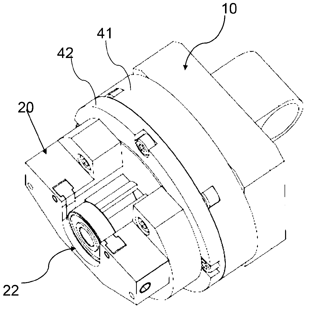
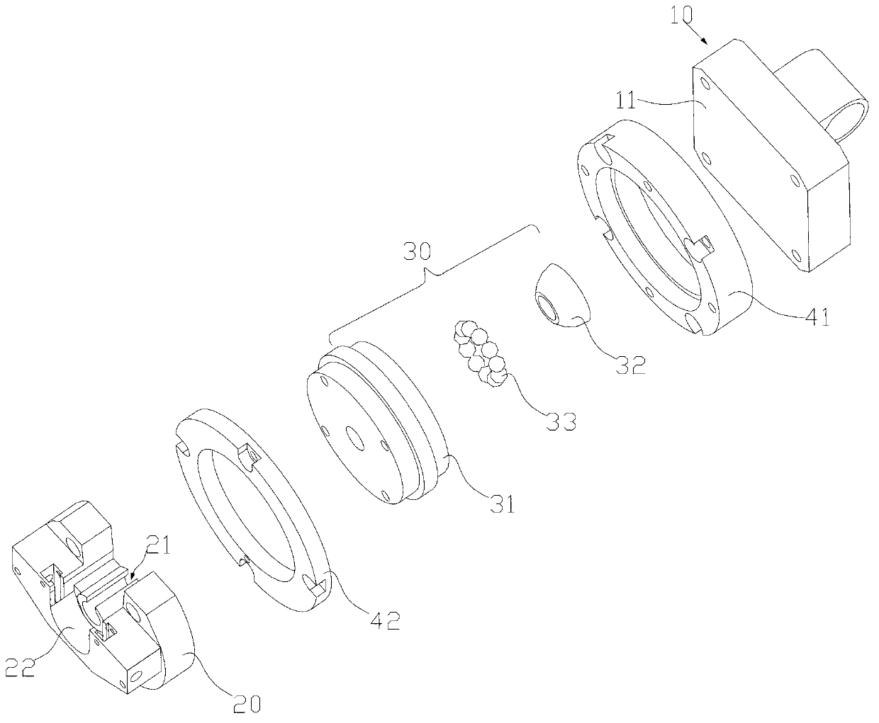
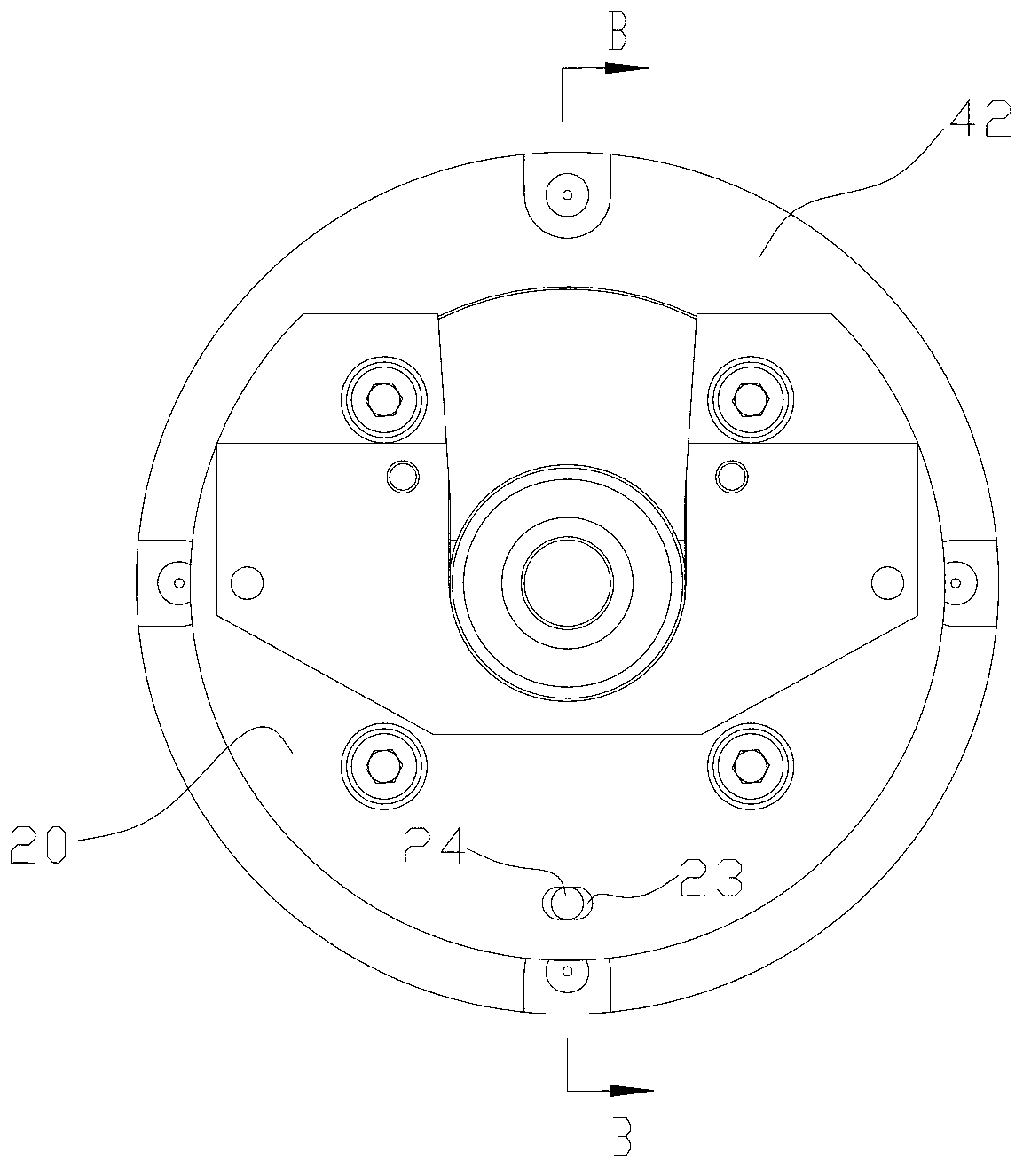
[0013] Such as Figure 1-3 , a centering device for press-fitting bearings, including a bracket 10 and a support 20 for placing the bearing to be assembled. The support 20 is provided with a hole 21 for the shaft to be assembled to pass through. Between the support 20 and the bracket 10 A self-aligning bearing assembly 30 is provided, and the inner and outer rings of the self-aligning bearing assembly 30 are respectively connected to the bracket 10 at the support 20 . The inner ring and the outer ring of the self-aligning bearing assembly 30 can float with each other, and the axes of the two may not coincide, that is to say, the axis of the outer ring can be deflected relative to the axis of the inner ring, so the support 20 connecting the outer ring It can be deflected and floated relative to the bracket 10, and there is a movable fit between the two. When press-fitting the bearing, the rotor shaft passes through the inner hole of the bearing to be assembled and overhangs to...


PUM


Abstract

The invention relates to the field of motor rotors, in particular to a center-adjusting device for pressing and assembling a bearing. The center-adjusting device for pressing and assembling the bearing comprises a supporting frame and a support which is used for accommodating the bearing to be assembled. A hole through which a rotating shaft to be assembled can pass is formed in the support, and a center-adjusting bearing assembly is arranged between the support and the supporting frame. An inner ring and an outer ring of the center-adjusting bearing assembly are connected with the support and the supporting frame respectively, the inner ring and the outer ring of the center-adjusting bearing assembly can mutually float, the axis of the inner ring and the axis of the outer ring can not be overlapped, and therefore the support connected with the outer ring can float relative to the supporting frame. When the bearing is pressed and assembled, the rotating shaft of a rotor penetrates through an inner hole of the bearing and then extends into the hole in the support in a hanging mode. When the axis of the bearing and the axis of the rotating shaft are not located in the same straight line, the support can swing in a deviation mode along with the extending of the rotating shaft until the axis of the bearing and the axis of the rotating shaft are overlapped. Therefore, the center can be automatically adjusted when the bearing is pressed and assembled, the concentricity of the bearing and the rotating shaft is guaranteed, and the quality of the rotator is improved.

Description

technical field [0001] The invention relates to the field of motor rotors, in particular to an aligning device for press-fitted bearings. Background technique [0002] Bearings need to be installed on the rotating shaft of the motor rotor. At present, the bearings are directly pressed onto the rotating shaft. There is no alignment before installation. In addition, there will be tolerances in the dimensions of the rotating shaft and bearings. The concentricity of the ring has to be firmly pressed on the shaft. If the axes of the shaft and the bearing are not on the same line during the assembly process, such installation will cause the shaft and bearing to be deformed by stress after assembly, resulting in increased noise of the rotor. When the noise is too large, the bearings need to be removed and re-installed, which wastes a lot of bearings, increases the production cost and also increases the workload and reduces the work efficiency. Contents of the invention [0003] ...

Claims


Application Information

Patent Timeline
IPC IPC(8): B23P19/10B23P19/02
Inventor 解永彬
Owner 合肥凯邦电机有限公司
Learn More