
A sliding door and window limit switch

A limit switch and sliding type technology, which is applied in the direction of building fastening devices, wing leaf fastening devices, buildings, etc., can solve the problems that affect the overall appearance of doors and windows, inconvenient operation, poor durability, etc., and achieve a beautiful appearance Compact, compact and ingenious structure, strong concealment effect

Inactive Publication Date: 2015-12-02
NINGBO IDEAL HARDWARE IND & TRADE
View PDF8 Cites 0 Cited by
  • Summary
  • Abstract
  • Description
  • Claims
  • Application Information

AI Technical Summary

Problems solved by technology

[0002] Sliding doors and windows are generally composed of doors, windows and guide rails, which can be seen in commercial housing, office buildings or ordinary residential buildings today. Such doors and windows are easy to open and close and are also wind-resistant, but usually do not have a limit function. For indoor For children, the slightly opened doors and windows are easy to open or close, resulting in safety accidents such as climbing out of the doors and windows or pinching their hands. For outdoor thieves, it is also easy for them to open the slightly opened doors and windows to enter indoor burglary
For this reason, people have designed a suction cup type limiting device, which is adsorbed on the doors and windows through the suction cup. Although it has a certain limiting effect, it greatly affects the overall appearance of the doors and windows. The quality of its limiting function also depends on the suction cup. In order to have a satisfactory effect, people often have to repeat the adsorption many times, thus reducing the use efficiency. People also realize that the adsorption force of the suction cup is limited after all during regular use, and it is necessary to seek improvement in the fixing method.
Chinese patent CN201116425Y discloses a movable door and window stop block structure, including a base plate, a baffle plate is movable and pivoted on the base plate, and the base plate is provided with an embedded stopper and a fastener that can be snapped and positioned with the baffle plate , the main body is installed near the door and window through the fastener. This fixing method is more stable than the above-mentioned suction cup type, which can effectively prevent the sliding of the door and window, but its structure is relatively complicated, which means that the volume is large, and the whole device is exposed to the outside , it is easy to accompany the feet when installed on the threshold, and the device is inconvenient to operate, and the durability of various components is relatively poor

Method used


Image

  • A sliding door and window limit switch
  • A sliding door and window limit switch
  • A sliding door and window limit switch

Examples


Embodiment Construction

[0019] The following are specific embodiments of the present invention and in conjunction with the accompanying drawings, the technical solutions of the present invention are further described, but the present invention is not limited to these embodiments.

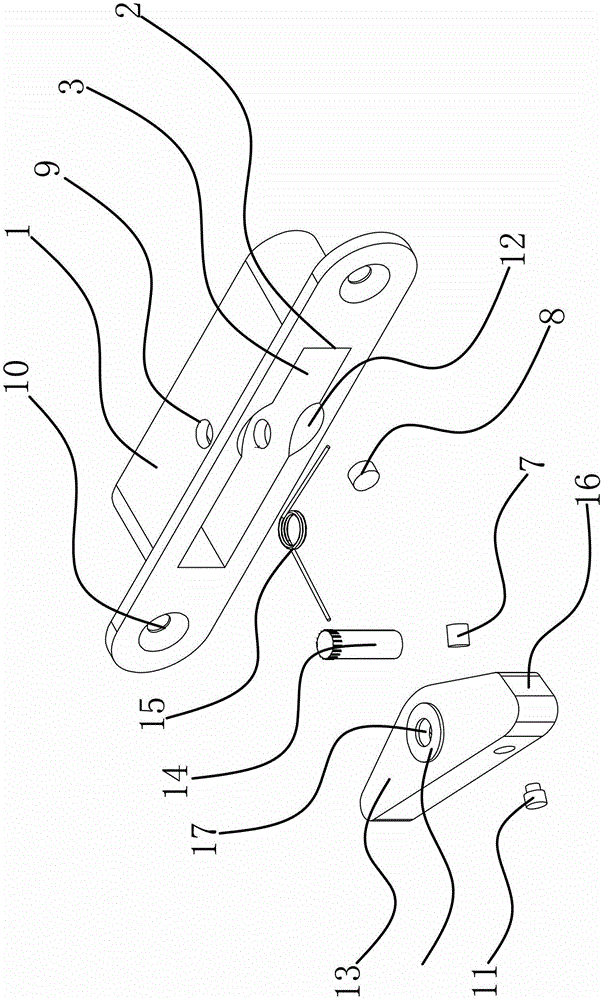
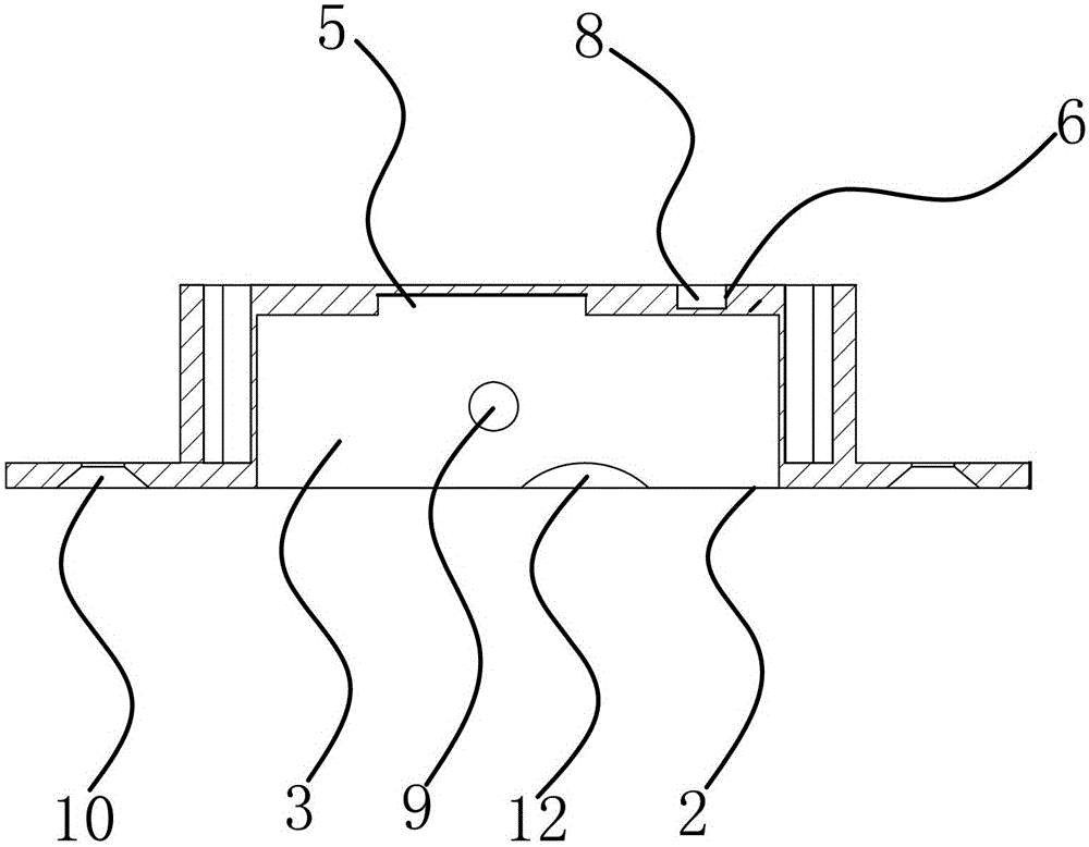
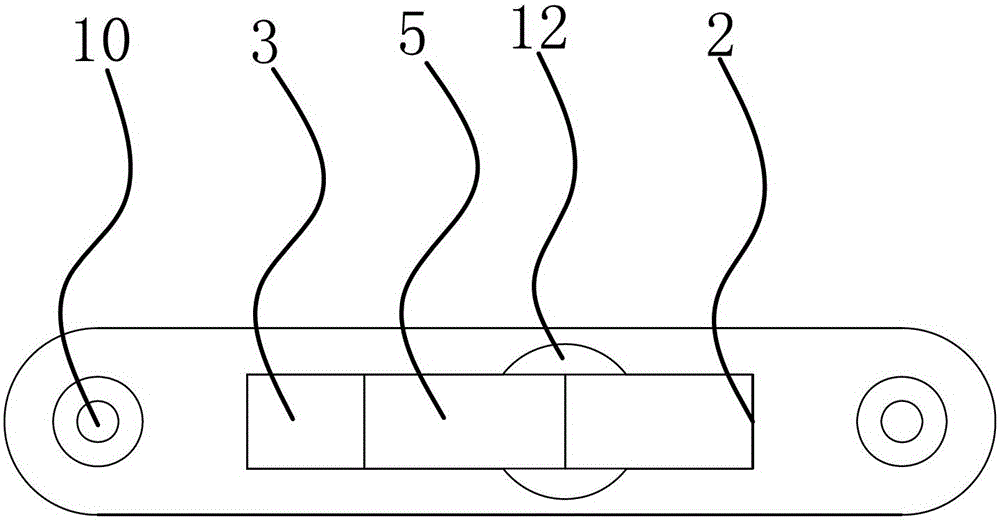
[0020] like figure 1 , figure 2 and image 3 As shown, a sliding door and window limit switch includes a metal switch base 1, the switch base 1 is in the shape of a long strip, and a cavity 3 with an opening 2 is provided on the switch base 1, and the middle part of the bottom surface of the cavity 3 is There is a groove two 5, the bottom surface of the cavity 3 is located on one side of the groove two 5, and a groove three 6 is provided, and a magnetic block two 8 is installed in the groove three 6, and one end surface of the magnetic block two 8 is connected to the switch base The bottom surface of 1 is flush, and the other end surface is close to the bottom surface of cavity 3. A circular hole 9 for fixing pin shaft ...


PUM


Abstract

The invention relates to a switch for limiting the movement of doors and windows and belongs to the field of machinery. A conventional inhibiting device is complicated in structure and inconvenient to operate and has relatively poor durability. The switch comprises a metallic switch base which is fixedly arranged on a door and window sliding rail, wherein a cavity with an opening is formed in the switch base, a torsional spring, a pin shaft and a limited block are arranged in the cavity, a groove I capable of containing the torsional spring is formed in one side of the limited block, which faces towards the bottom surface of the cavity, a magnetic block I is arranged in one side of the limited block, which faces towards the bottom surface of the cavity and in a place adjacent to the groove I, the pin shaft sequentially penetrates through the limited block and the torsional spring along the width direction of the switch base and is fixedly arranged in the middle of the side wall of the switch base, and under the action of the torsional spring, one end of the limited block extends out of the cavity, and the other end of the limited block is positioned at the bottom of the cavity. Due to adoption of the structure, the switch has an exquisite and compact appearance, strong concealment and enduring and stable functions, is compact and ingenious in structure, durable in use, easy and convenient to operate and suitable for the multiple slippage-type doors and windows.

Description

technical field [0001] The invention belongs to the mechanical field and relates to a switch, in particular to a switch for limiting the movement of doors and windows. Background technique [0002] Sliding doors and windows are generally composed of doors, windows and guide rails, which can be seen in commercial housing, office buildings or ordinary residential buildings today. Such doors and windows are easy to open and close and are also wind-resistant, but usually do not have a limit function. For indoor For children, the slightly opened doors and windows are easy to open or close, resulting in safety accidents such as climbing out of the doors and windows or pinching their hands. For outdoor thieves, it is also easy for them to open the slightly opened doors and windows to enter Indoor theft. For this reason, people have designed a suction cup type limiting device, which is adsorbed on the doors and windows through the suction cup. Although it has a certain limiting eff...

Claims


Application Information

Patent Timeline
Patent Type & Authority Patents(China)
IPC IPC(8): E05C17/00
Inventor 高欣璐
Owner NINGBO IDEAL HARDWARE IND & TRADE
Learn More