Fluid-driven pumping unit and method of application thereof

A fluid-driven, application-method technology, applied in the fields of fluid production, earth-moving drilling, wellbore/well components, etc., can solve the problems of small energy conversion and large energy conversion loss, and achieve small energy conversion loss, stable load, and energy saving good effect

Active Publication Date: 2015-11-11
山东高原油气装备有限公司
View PDF5 Cites 0 Cited by
  • Summary
  • Abstract
  • Description
  • Claims
  • Application Information

AI Technical Summary

Problems solved by technology

[0003] The present invention aims at the defect of large energy conversion loss in existing equipment, and provides a fluid-driven pumping unit with small energy conversion, good energy-saving effect, and variable balance according to different load conditions and its application method

Method used


Image

  • Fluid-driven pumping unit and method of application thereof

Examples


Embodiment Construction

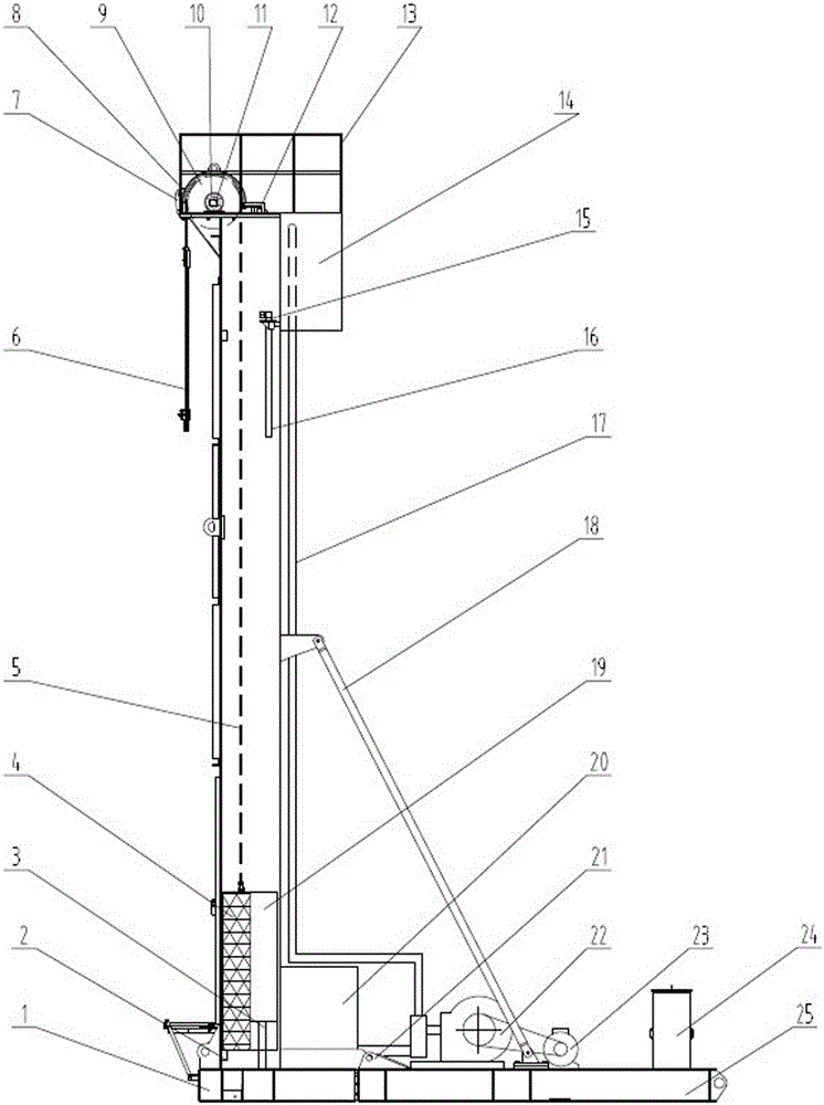
[0017] refer to figure 1 , a fluid-driven pumping unit, comprising a base assembly 25 and a frame assembly 1 connected thereto, with an oblique support rod 18 connected between them; a roller support 10 is installed on the top of the frame assembly, and a There is a drum 9, a belt 5 is wound on the upper surface of the drum 9, a speed detection device 11 is arranged on the drum shaft, and a brake device is installed on the drum 9, and the brake device includes a brake 8 and a brake drive device 12; the upper part of the frame assembly 1 The upper and lower fluid tanks 14, 20 are respectively fixed with the lower part, and the connection is established through the fluid lifting system 22 installed on the base assembly 25. The fluid lifting system 22 includes a pump (driven by a motor 23) and a liquid lifting tube 17. The upper part The bottom of the fluid box 14 is provided with a liquid conduit 16, on which an electromagnetic valve is installed; the frame assembly 1 is provide...


PUM


Abstract

The invention discloses a fluid driving pumping unit and an application method thereof. The fluid driving pumping unit structurally comprises a base and a machine frame connected to the base. A roller is arranged on the top of the machine frame, and a belt is wound on the roller. An upper fluid box is fixed on the upper portion of the machine frame, a lower fluid box is fixed on the lower portion of the machine frame, and the upper portion and the lower portion of the machine frame can be connected through a fluid lifting system installed on the base. The machine frame is further provided with a fluid driving box capable of moving up and down along the machine frame, when the driving box moves to the upper portion of the machine frame, the driving box can be communicated with the upper fluid box in a controlled mode, and when the driving box moves to the lower portion of the machine frame, the driving box can be communicated with the lower fluid box in a controlled mode. The upper portion of the fluid driving box is connected with the belt. According to the application method, a balanced box is driven through the circulation of fluid, and the belt is used for driving a sucker rod to do reciprocating movement up and down. Compared with the prior art, the fluid driving pumping unit has the advantages of being small in energy conversion loss, good in energy-saving effect, adjustable in stroke and stable in load. Variable balancing can be carried out according to different load situations.

Description

technical field [0001] The invention relates to the field of oil production machinery, in particular to an oil pumping unit which utilizes fluid circulation to realize reversing of the oil pumping unit. Background technique [0002] At present, there are many types of pumping units used in oil production in oilfields. The beam pumping unit has many parts, the installation is not fast enough and long, the production efficiency is low, and the equipment maintenance is complicated. In particular, there are many energy conversion links, which require strong power and consume a lot of energy. The hydraulic pumping unit does not have a balancing device and also consumes a lot of energy. Contents of the invention [0003] The present invention aims at the defect of large energy conversion loss in existing equipment, and provides a fluid-driven pumping unit with small energy conversion, good energy-saving effect and variable balance according to different load conditions and its ...

Claims


Application Information

Patent Timeline
Patent Type & Authority Patents(China)
IPC IPC(8): E21B43/00
Inventor 李培江
Owner 山东高原油气装备有限公司
Why Eureka
Try Eureka