Hydraulic sliding sleeve

A hydraulic sliding sleeve and hydraulic technology, which is applied in the direction of production fluid, wellbore/well components, earthwork drilling and production, etc., can solve the problems of limited number of fracturing stages, limited displacement, packer can not guarantee complete sealing, etc. Achieve the effect of increasing fracturing scale, improving reliability and realizing selective production

Active Publication Date: 2013-09-04
CHINA NAT OFFSHORE OIL CORP +1
View PDF7 Cites 23 Cited by
  • Summary
  • Abstract
  • Description
  • Claims
  • Application Information

AI Technical Summary

Problems solved by technology

The technology has the following problems in field application: (1) In the open hole section, the packer cannot guarantee complete sealing under high pressure, which will affect the segmentation effect; (2) The number of fracturing stages is limited by the use of step-by-step ball setting. ;(3) The quality of the borehole is high, and the drilling time is long. Generally, 4-5 well drillings are required after drilling, but there are still risks of drill sticking and failure of the pipe string to run in place.
(4) Fractures may occur in the well section between the two packers, and the location of the fractures is uncontrollable
The hydraulic sandblasting perforating technology has the following limitations: (1) the displacement is limited, the fracturing scale is small, and it is difficult to form long fractures and network fractures; (2) the nozzle is easy to wear, which limits the number of fracturing stages; (3) it cannot Realize post-selective production
[0007] From the above analysis, it can be seen that the above staged fracturing technologies are difficult to meet the requirements of high reliability and later stage selective production in offshore oilfields, and there is an urgent need for a short construction time, unlimited number of fracturing stages, which can achieve selectivity. Production horizontal well staged fracturing technology

Method used


Image

  • Hydraulic sliding sleeve
  • Hydraulic sliding sleeve
  • Hydraulic sliding sleeve

Examples


Embodiment Construction

[0037] Embodiments of the present invention will be described in detail below in conjunction with the accompanying drawings. It should be noted that, in the case of no conflict, the embodiments in the present application and the features in the embodiments can be combined arbitrarily with each other.

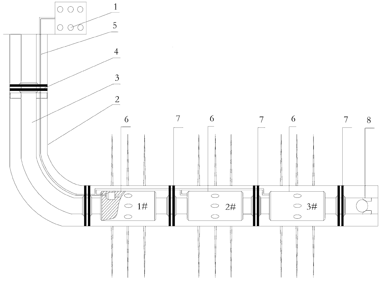
[0038] as attached figure 1 As shown, the completion string of the embodiment of the present invention includes a surface hydraulic control device, a casing 2, an oil pipe 3 arranged inside the casing 2, a hydraulic pipeline 5, and a tieback hanger 4, which are sequentially connected with the oil pipe 3 in the horizontal section Multiple fracturing construction units and the sealing unit at the bottom of the pipe string;

[0039] The fracturing construction unit is sequentially provided with a hydraulic packer 7 and a hydraulic sliding sleeve 6; the bottom end seating unit of the pipe string is sequentially provided with a hydraulic packer 7 and a ball seat 8 connected to the t...


PUM


Abstract

The invention provides a hydraulic sliding sleeve which comprises a measuring and controlling system, a driving system, a power supplying system and hydraulic channels or hydraulic cavities. The measuring and controlling system is used for detecting pressure variation of hydraulic pressure in each hydraulic channel or each hydraulic cavity and then transmitting instructions to the driving system according to detection results, so that the hydraulic sliding sleeve can be opened or closed; and the power supplying system provides electric energy for the measuring and controlling system and the driving system. The hydraulic sliding sleeve in an embodiment of the invention has the advantages that when hydraulic sliding sleeves are applied to a completion string of a horizontal well, the hydraulic pressures (used as control signals) with the pressure variation are generated by a ground hydraulic control device and are transmitted to the hydraulic sliding sleeves in various fracturing construction units of a horizontal section, the hydraulic sliding sleeves only can be opened or closed after receiving the respective pressure signals, accordingly, step-by-step ball feeding is omitted, and unlimited staged fracturing can be implemented for the horizontal section; and later staged production can be implemented, and the hydraulic sliding sleeve is quite suitable for marine staged fracturing.

Description

technical field [0001] The invention relates to equipment for oil and gas field development, in particular to a hydraulic sliding sleeve. Background technique [0002] The low-permeability reservoirs in offshore oilfields are rich in reserves, and the current recovery level is low. There is an urgent need for horizontal well staged fracturing technology. However, due to offshore oilfield production operations, horizontal well staged fracturing technology must have very high reliability. Due to the high operating cost and small platform area of ​​offshore oilfields, staged fracturing of horizontal wells in offshore oilfields has not been carried out in China so far. [0003] At present, there are more than ten kinds of staged fracturing technologies for horizontal wells in domestic and foreign oilfields, among which three are the most widely used technologies, which are packer-sliding sleeve staged fracturing technology, hydraulic sandblasting and perforating fracturing techn...

Claims


Application Information

Patent Timeline
Patent Type & Authority Applications(China)
IPC IPC(8): E21B43/26E21B34/08
Inventor 董社霞赵利昌张海龙朱春明季公明刘新峰刘正伟张保康王圣虹刘明娟
Owner CHINA NAT OFFSHORE OIL CORP
Why Eureka
Try Eureka