
A side -light backlight module and electronic device

A backlight module and side-light technology, which is applied in the field of side-light backlight modules and electronic equipment, can solve problems such as difficult production and complex structure of light guide plates

Active Publication Date: 2015-09-09
HISENSE VISUAL TECH CO LTD
View PDF5 Cites 0 Cited by
  • Summary
  • Abstract
  • Description
  • Claims
  • Application Information

AI Technical Summary

Problems solved by technology

[0014] Embodiments of the present invention provide an edge-lit backlight module and electronic equipment, which are used to solve the technical problems of complex structure and difficult manufacture of the light guide plate caused by alleviating the problem of light spots in the prior art

Method used


Image

  • A side -light backlight module and electronic device
  • A side -light backlight module and electronic device
  • A side -light backlight module and electronic device

Examples


Embodiment 1

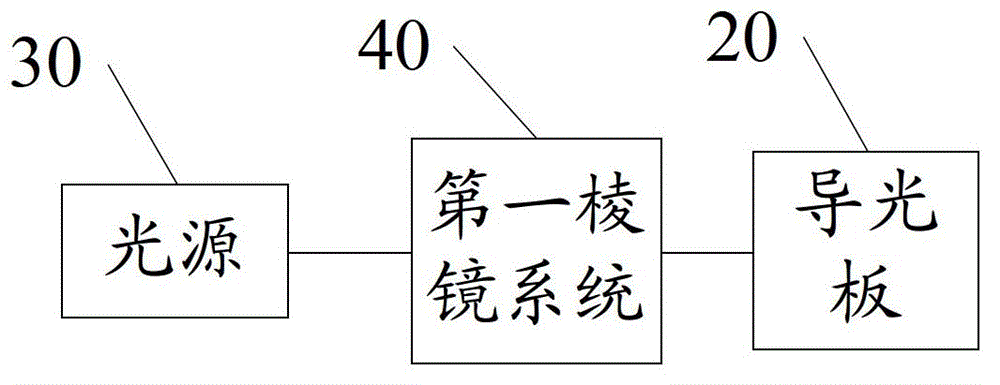
[0031] Embodiment 1 of this application provides an edge-lit backlight module, please refer to figure 2 , figure 2 It is a functional block diagram of the edge-lit backlight module in this embodiment. The edge-lit backlight module includes:

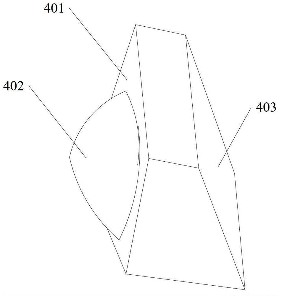
[0032] The light guide plate 20 has a light incident surface and a light exit surface adjacent to the light incident surface; the light source 30 is arranged opposite to the light incident surface; the first prism system 40 is arranged between the light source 30 and the light incident surface; wherein, when the light source The radial first incident light generated by 30 passes through the prism system 40, first refracted into first parallel light, and then converted into parallel second incident light by the first parallel light, and the second incident light forms on the light incident surface The first incident region is elliptical, the long axis of the ellipse is parallel to the common edge adjacent to the light incident surface ...

Embodiment 2

[0066] Based on the same inventive concept, Embodiment 2 of the present application provides an electronic device, such as a TV set and a liquid crystal display, please refer to Figure 7 , the electronic equipment includes the following structure:

[0067] Chassis 61;

[0068] A processor 62 is arranged in the casing 61;

[0069] The display unit 63 is arranged on the casing 61 and connected to the processor 62, wherein the display unit 63 includes:

[0070] Liquid crystal panel 63a;

[0071] The side-light backlight module 63b introduced in Embodiment 1 of this application is connected to the liquid crystal panel 63a, wherein the liquid crystal panel 63a is set on the surface of the side-light backlight module 63b, and the side-light backlight module 63b The backlight module 63b can provide backlight for the liquid crystal panel 63a.


PUM


Abstract

The invention discloses an edge lighting backlight module and electric equipment. The edge lighting backlight module comprises a light guide plate, a light source and a prism system, wherein the light guide plate is provided with a light-in face and a light-out face which is adjoined with the light-in face, the light source is arranged opposite to the light-in face, and the prism system is arranged between the light source and the light-in face. First radial incident light generated by the light source is incident on the prism system to be refracted into first parallel light with a circular cross section, the first parallel light is converted into second parallel incident light, a first incident area formed by the second incident light on the light-in face is in an oval shape, an oval long shaft is parallel to the adjoining shared edge of the light-in face and the light-out face, and the length of the long shaft is larger than the length of the diameter of the circular cross section of the first parallel light.

Description

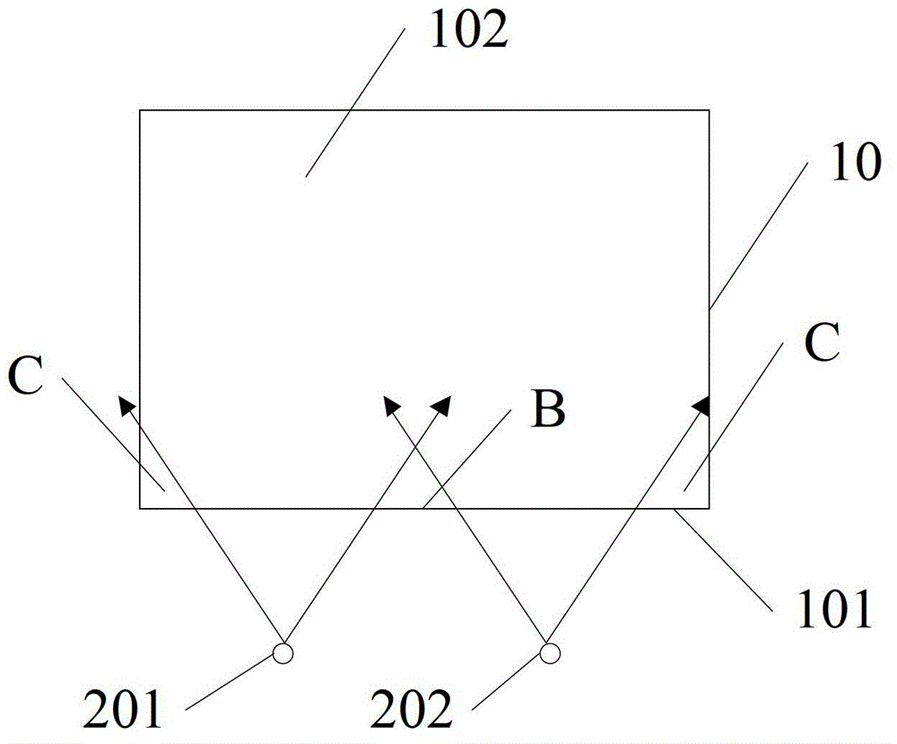
technical field [0001] The invention relates to the field of display technology, in particular to an edge-light backlight module and electronic equipment. Background technique [0002] With the development of electronic technology, more and more electronic devices have been produced, among which, many electronic devices have liquid crystal display screens. Usually, liquid crystal display screens include liquid crystal panels and backlight modules. The liquid crystal panels are composed of two layers A liquid crystal layer is sandwiched between glass substrates. Since the liquid crystal panel itself does not emit light, a uniform light source system needs to be provided for it through the backlight module. [0003] In the prior art, usually, backlight modules include: direct-type backlight modules and edge-type backlight modules, among which, please refer to figure 1 , the edge-lit backlight module includes the following structure: [0004] The light guide plate 10 specific...

Claims


Application Information

Patent Timeline
Patent Type & Authority Patents(China)
IPC IPC(8): G02F1/13357G02B6/00F21V13/02
CPCG02B6/0025G02F1/133606G02F1/133607
Inventor 张登印黄奔
Owner HISENSE VISUAL TECH CO LTD
Learn More