Device for processing large-size flange surface

A large-scale flange and surface processing technology, which is applied in the direction of metal processing equipment, manufacturing tools, milling machine equipment details, etc., can solve problems such as the impact of processing accuracy, and achieve the effects of improving processing accuracy, shortening processing time, and flexible use

Inactive Publication Date: 2013-09-11
CHINA GEZHOUBA GROUP MACHINERY & SHIP
View PDF8 Cites 6 Cited by
  • Summary
  • Abstract
  • Description
  • Claims
  • Application Information

AI Technical Summary

Problems solved by technology

The problem is that due to the long length of the slewing arm and the gap in the central axis, the gap value is magnified by the slewing arm, which affects the machining accuracy

Method used


Image

  • Device for processing large-size flange surface
  • Device for processing large-size flange surface
  • Device for processing large-size flange surface

Examples


Embodiment 1

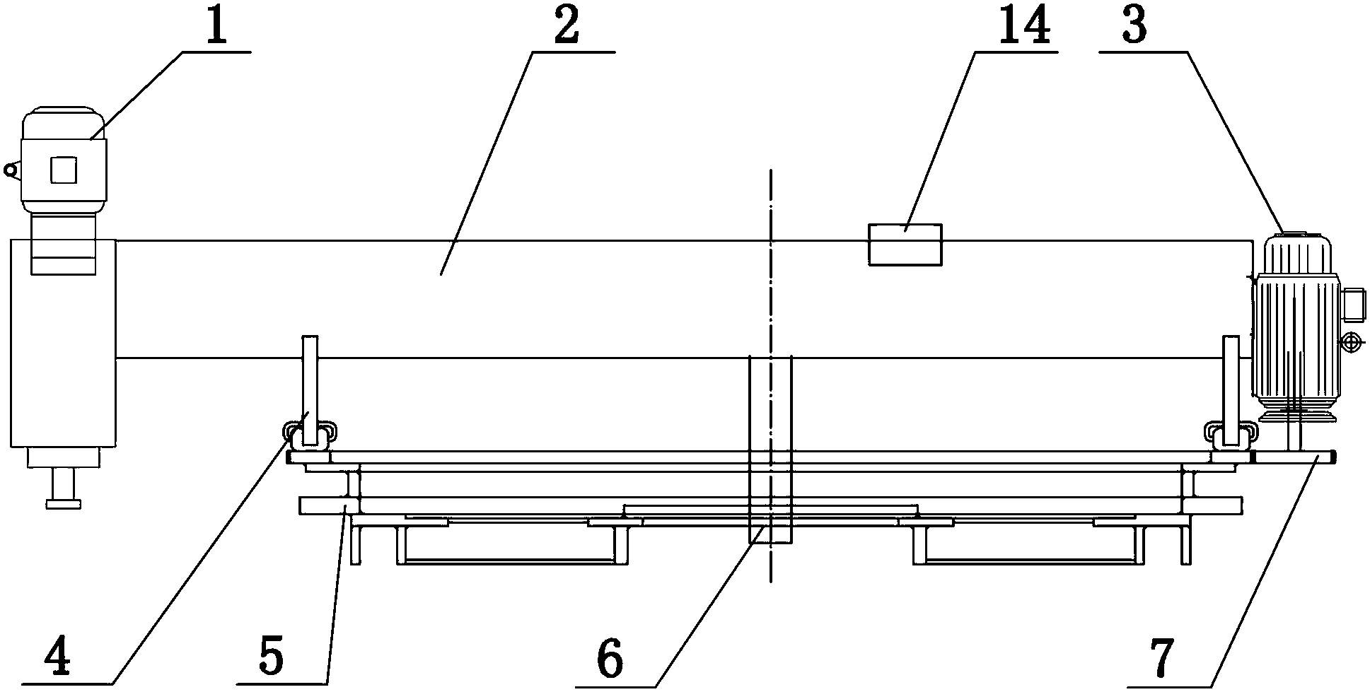
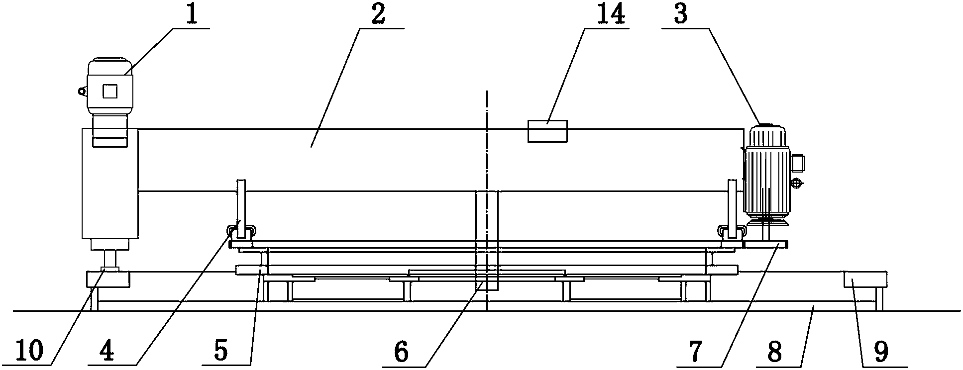
[0025] Such as figure 1 , 2 Among them, a device for large-scale flange surface processing, including a milling cutter 10 driven by a milling cutter driving device 1, the milling cutter 10 and the milling cutter driving device 1 are installed at one end of the processing arm 2 for driving the processing arm 2 The rotating arm rotation driving device 3 is installed on the other end of the processing arm 2; the milling cutter driving device 1 in this example includes a milling cutter rotating driving device and a feed driving device, and in a preferred solution, the milling cutter driving device 1 passes through the telescopic arm (11) is movably connected with the processing arm 2 through guide rails. Since the structure of the milling cutter driving device 1 can be obtained in the prior art, it will not be repeated here.

[0026] A main shaft 6 is provided near the middle of the processing arm 2, and the processing arm 2 rotates around the main shaft; this structure ensures ...

Embodiment 2

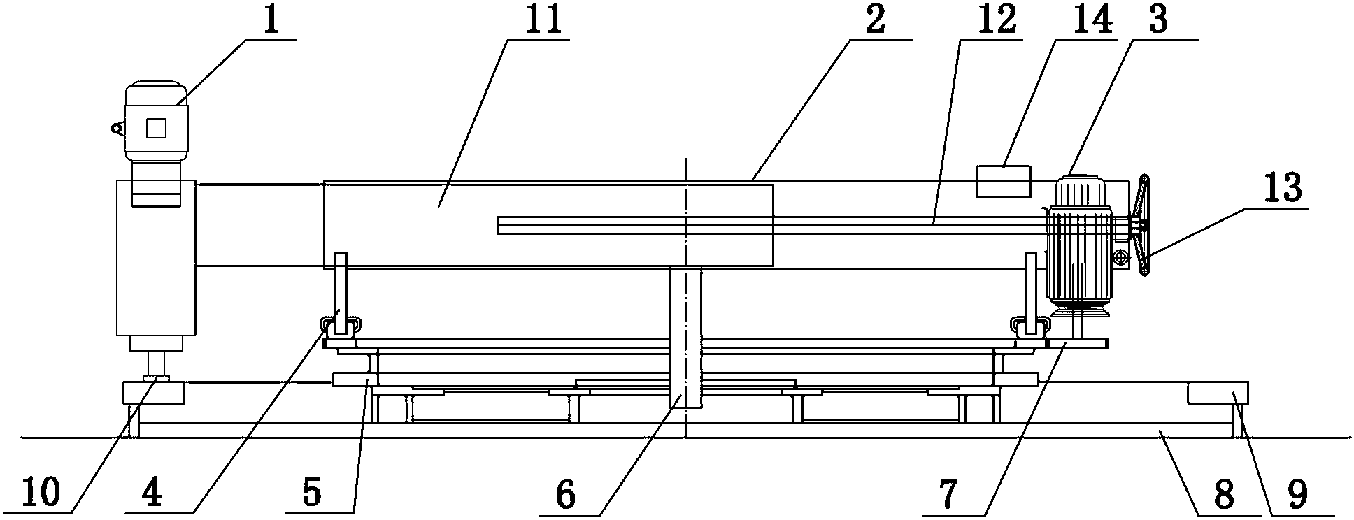
[0037] Such as image 3 Among them, a device for large-scale flange surface processing, including a milling cutter 10 driven by a milling cutter driving device 1, the distance between the milling cutter driving device 1 and the processing arm 2 can be adjusted to the main shaft 6 active connection. The milling cutter driving device 1 is installed at one end of the telescopic arm 11 , the telescopic arm 11 is movably connected with the processing arm 2 through a guide rail, and the other end of the telescopic arm 11 is provided with a nut connected with the screw rod 12 . The free end of the screw rod 12 is provided with a hand wheel 13 .

[0038] A main shaft 6 is provided near the middle of the processing arm 2, and the processing arm 2 rotates around the main shaft;

[0039] The position close to the edge of the flange 9 to be processed on the processing arm 2 is also provided with a tightening adjustment roller 4 for adjusting the level of the processing arm 2 .

[0040]...


PUM


Abstract

The invention discloses a device for processing a large-size flange surface. The device comprises a milling cutter driven by a milling cutter driving device, wherein the milling cutter and the milling cutter driving device are arranged at one end of a processing arm; an arm rotation driving device for driving the processing arm to rotate is arranged at the other end of the processing arm; a main shaft is arranged at a position, which is close to the middle of the processing arm, on the processing arm; the processing arm rotates around the main shaft serving as a center; a pressing adjustment roller for adjusting the levelness of the processing arm is also arranged at a position, which is close to the edge of a flange to be processed, on the processing arm. By adopting a structure that the milling cutter driving device and the arm rotation driving device are respectively arranged at the two ends of the processing arm, the device is favorable for in-site processing of the large-size flange surface. The arm rotation driving device also serves as a balance weight matched with the milling cutter driving device. A chassis tooth ring with a larger diameter is more reliable in stress, so that the levelness of the processing arm can be further guaranteed. Due to the pressing adjustment roller, the influence caused by a main shaft clearance and deformation of a material on the processing precision can be effectively reduced.

Description

technical field [0001] The invention relates to the field of flange processing, in particular to a device for processing the end faces of large flange parts. Background technique [0002] In the past, the flange surface processing on large structural parts has always been a difficult problem. Due to the large size of large structural parts, it is impossible to process the flange surface on a conventional milling machine. Instead, the flange surface is processed separately and then the structural part Tailored welding, the deformation of components is not easy to control, and the levelness is also difficult to meet the construction requirements, such as the flange surface processing on the support cylinder of the floating crane. [0003] Publication number is that the Chinese patent document of 201644883U discloses a kind of special-purpose milling machine for processing the flange end face, has adopted the structure processing the end face of large-scale flange structural me...

Claims


Application Information

Patent Timeline
Patent Type & Authority Applications(China)
IPC IPC(8): B23C3/00
Inventor 彭景亮李丽丽陈爱国沈赓廖全勇张庆军
Owner CHINA GEZHOUBA GROUP MACHINERY & SHIP
Why Eureka
Try Eureka