Continuous changeable air inlet tumbling flow control mechanism of engine and engine

A control mechanism and engine technology, applied in engine control, combustion engine, machine/engine, etc., can solve the problem of variable tumble flow not working, and achieve the effect of improving airflow movement and better tumble flow effect.

Active Publication Date: 2013-09-11
GREAT WALL MOTOR CO LTD
View PDF6 Cites 2 Cited by
  • Summary
  • Abstract
  • Description
  • Claims
  • Application Information

AI Technical Summary

Problems solved by technology

The butterfly valve is closed at startup and idle conditions, which can effectively improve the combustion conditions under these conditions. In other conditions, such as low-to-medium speed or low-to-medium load, strong tumble motion is also required, but the two working conditions When the butterfly valve is open, the variable tumble does not work

Method used


Image

  • Continuous changeable air inlet tumbling flow control mechanism of engine and engine
  • Continuous changeable air inlet tumbling flow control mechanism of engine and engine
  • Continuous changeable air inlet tumbling flow control mechanism of engine and engine

Examples


Embodiment 1

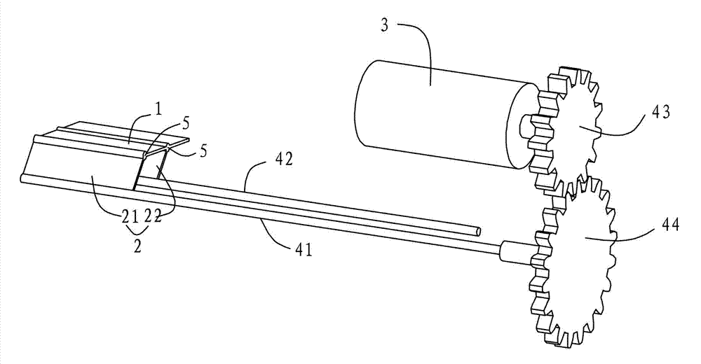
[0023] This embodiment relates to a continuously variable intake tumble control mechanism for an engine, which is arranged in the intake pipe of the engine, and is composed of figure 1 As shown, it includes a top plate 1 arranged horizontally in the state shown in the figure, a support blocking device 2 connected to the bottom of the top plate 1 , and a power transmission mechanism connected between the support blocking device 2 and the power output device 3 . The power is transmitted to the support and blocking device 2 through the power transmission mechanism, so that the support and blocking device 2 drives the top plate to have a vertical displacement while keeping the top plate 1 in a horizontal state. In this embodiment, the power output device 3 adopts a servo motor.

[0024] Wherein, the support blocking device 2 comprises a first side plate 21 and a second side plate 22 of the same size that are arranged in parallel and connected below the top plate 1, and the first s...

Embodiment 2

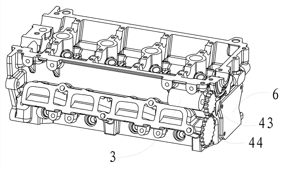
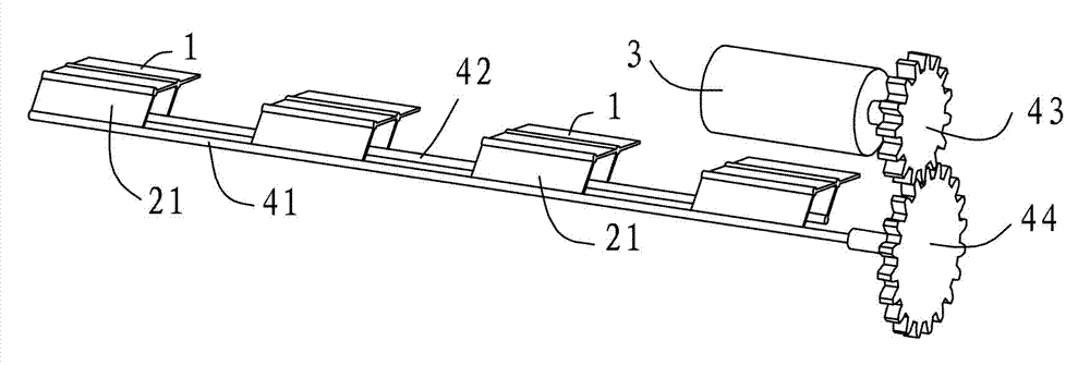
[0029] This embodiment relates to an engine, which is an application of the continuously variable intake tumble control mechanism of the engine involved in the first embodiment. Depend on figure 2 combine image 3 As shown, the engine of this embodiment has four intake ducts, each of which is provided with the continuously variable intake tumble flow control mechanism of the engine involved in the first embodiment. Depend on image 3 As shown, the continuously variable intake tumble control mechanism of the engine is basically the same as the first embodiment, the difference is that four sets of supporting and blocking devices 2 are used to cooperate with the top plate 1, and one rotating shaft 41, one Root driven shaft 42, a power output device 3 and a speed reduction structure.

[0030] Depend on figure 2 As shown, the power take-off device 3 is fixedly arranged on the main body 6 of the engine, and the rotating shaft 41 connected with the driven gear 44 penetrates fro...


PUM


Abstract

The invention relates to a device for adjusting air flow in an air inlet pipeline of an engine, in particular to a continuous changeable air inlet tumbling flow control mechanism of the engine. The continuous changeable air inlet tumbling flow control mechanism of the engine comprises a top plate, a supporting stopping device and a power transmission mechanism, wherein the supporting stopping device is used for supporting the top plate and carrying out stopping on the air flow in the air inlet pipeline, and the power transmission mechanism is arranged between the supporting stopping device and a power output device in a connected mode. Meanwhile, the invention further relates to the engine with the continuous changeable air inlet tumbling flow control mechanism. According to the technical scheme, the area of an unblocked channel formed above the top plate can be adjusted at any time, and continuous changeable performance of air inlet tumbling flow can be achieved.

Description

technical field [0001] The invention relates to a device for adjusting airflow in an engine intake duct, in particular to an engine continuously variable intake tumble flow control mechanism, and at the same time, the invention also relates to an engine with the control mechanism. Background technique [0002] Direct injection gasoline engine is recognized as one of the important technologies for automobile energy saving and emission reduction. Compared with port injection gasoline engine, it has faster transient response, lower cold start emission, quick start and stop and high thermal efficiency, and can realize stratified combustion. The supercharging technology can further realize the reduction and strengthening of the engine cylinder, so as to achieve the purpose of reducing the weight of the whole vehicle and reducing fuel consumption. Because the oil-air mixing process is carried out in the cylinder, the quality of the oil-air mixing directly affects the success or fa...

Claims


Application Information

Patent Timeline
Patent Type & Authority Applications(China)
IPC IPC(8): F02B31/06F02D9/02F02D9/08
CPCY02T10/12
Inventor 孙小伟宋东先杨红天
Owner GREAT WALL MOTOR CO LTD
Why Eureka
Try Eureka