
Dynamic heat dissipation led lighting

An LED lighting, dynamic technology, applied in lighting devices, lighting and heating equipment, cooling/heating devices of lighting devices, etc., can solve the problems of strong temperature sensitivity, limited heat dissipation effect, huge heat generation, etc. The effect of airflow movement and good heat dissipation

Active Publication Date: 2017-05-24
中山市中宏电器有限公司
View PDF5 Cites 0 Cited by
  • Summary
  • Abstract
  • Description
  • Claims
  • Application Information

AI Technical Summary

Problems solved by technology

[0002] At present, due to the good energy-saving effect of LED lighting, it has been widely promoted; and a problem encountered in the promotion process is that for high-brightness LED lights, the heat is huge, and LED chips are sensitive to temperature. In high temperature conditions, the performance of the LED will quickly decay, therefore, for a LED lamp with a small volume, it is usually necessary to configure a huge radiator; therefore, the problem of heat dissipation is a major factor restricting the promotion of LED lighting devices. question
[0003] At present, the design of the heat dissipation structure of LED lighting mainly improves the heat dissipation effect by improving the shape and distribution of the heat dissipation fins, but no matter how it is changed, since the current heat dissipation fins are fixed, it can only rely on natural The way of heat dissipation is to dissipate heat to the outside, and its heat dissipation effect is extremely limited; and for some structures with higher requirements, a motor fan structure is configured to perform forced convection heat dissipation. In addition to the cost of the motor itself, it is also necessary to consider the waterproofing of the motor. The cost of the structure leads to a substantial increase in the cost of the heat sink, which is also not conducive to popularization and application

Method used


Image

  • Dynamic heat dissipation led lighting
  • Dynamic heat dissipation led lighting
  • Dynamic heat dissipation led lighting

Examples


Embodiment Construction

[0014] Below in conjunction with accompanying drawing and embodiment the present invention is further described:

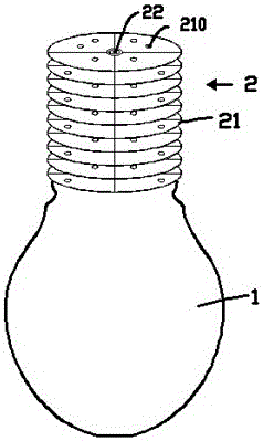
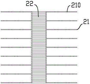
[0015] exist figure 1 , figure 2 In the shown embodiment, the dynamic heat dissipation LED lighting lamp includes a lamp body 1 and a radiator 2; the radiator 2 and the lamp body 1 are fixed to each other; the radiator 2 includes a large number of soft magnetic heat sinks distributed in parallel at equal distances twenty one. The number of cooling fins 21 is preferably 8-20; soft iron sheets or silicon steel sheets can be used, the thickness of which is less than 0.5 mm, and the surface can also be plated with copper or aluminum to improve heat dissipation efficiency.

[0016] In this embodiment, each heat sink 21 is in the shape of a disc, and its circular periphery can be bent freely when subjected to a force perpendicular to the surface of the heat sink; the distance between each heat sink 21 is 3 mm to 8 mm.

[0017] An electromagnet 22 is fixed in the cen...


PUM


Abstract

The present invention provides a dynamic heat dissipation LED lighting lamp. The dynamic heat dissipation LED lighting lamp includes a lamp body and a radiator; the radiator and the lamp body are fixed to each other; the radiator includes a large number of soft magnetic heat sinks distributed in parallel at equal distance , each cooling fin has a freely bendable periphery; an electromagnet is fixed in the center of the whole formed by each of the soft magnetic cooling fins; the electromagnet is electrically connected to alternating current. The LED illuminating lamp can adopt a heat sink with a smaller volume to achieve a good heat dissipation effect.

Description

technical field [0001] The present invention relates to the field of lighting equipment, in particular to an LED lighting lamp. Background technique [0002] At present, due to the good energy-saving effect of LED lighting, it has been widely promoted; and a problem encountered in the promotion process is that for high-brightness LED lights, the heat is huge, and LED chips are sensitive to temperature. In high temperature conditions, the performance of the LED will quickly decay, therefore, for a LED lamp with a small volume, it is usually necessary to configure a huge radiator; therefore, the problem of heat dissipation is a major factor restricting the promotion of LED lighting devices. question. [0003] At present, the design of the heat dissipation structure of LED lighting mainly improves the heat dissipation effect by improving the shape and distribution of the heat dissipation fins, but no matter how it is changed, since the current heat dissipation fins are fixed, ...

Claims


Application Information

Patent Timeline
Patent Type & Authority Patents(China)
IPC IPC(8): F21K9/232F21V29/85F21V29/76F21V29/83H05B33/08F21Y115/10H05B44/00
Inventor 李继洪
Owner 中山市中宏电器有限公司
Learn More