Novel magnetic snap

A magnetic buckle, a new type of technology, is applied in the direction of fasteners, clothing, connecting components, etc., which can solve the problems of inconvenient operation and achieve the effect of convenient operation and tight buckle

Active Publication Date: 2013-09-11
林汉雄
View PDF5 Cites 7 Cited by
  • Summary
  • Abstract
  • Description
  • Claims
  • Application Information

AI Technical Summary

Problems solved by technology

Although this kind of magnetic buckle structure is simple, it is inconvenient to operate, especially if it is necessary to improve the fastening tightness of the male buckle and the female buckle so as to increase the magnetic element polarity in the male buckle and the magnetic element in the female buckle. More force is required to separate the pin from the box

Method used


Image

  • Novel magnetic snap
  • Novel magnetic snap
  • Novel magnetic snap

Examples


Embodiment 1

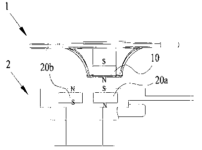
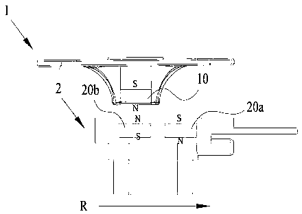
[0037] Embodiment 1 of the present invention provides a new type of magnetic buckle, including a first fastener 1 and a second fastener 2, the first fastener 1 is detachably mounted on the second fastener 2, and the first fastener 1 The first magnetic element 10 is set, and the second magnetic element 20a and the third magnetic element 20b are arranged side by side in the second fastener 2, and the second magnetic element 20a and the third magnetic element 20b can be made parallel to the first magnetic element 10 together. Linear movement, when the second magnetic element 20a is opposite to the first magnetic element 10, the polarity of the opposite surface is opposite to make the first fastener 1 and the second fastener 2 due to the first magnetic element 10 and the second magnetic element 20a Mutual attraction and fastening; when the third magnetic element 20b is opposite to the first magnetic element 10, the polarity of the opposite surface is the same so that the first fast...

Embodiment 2

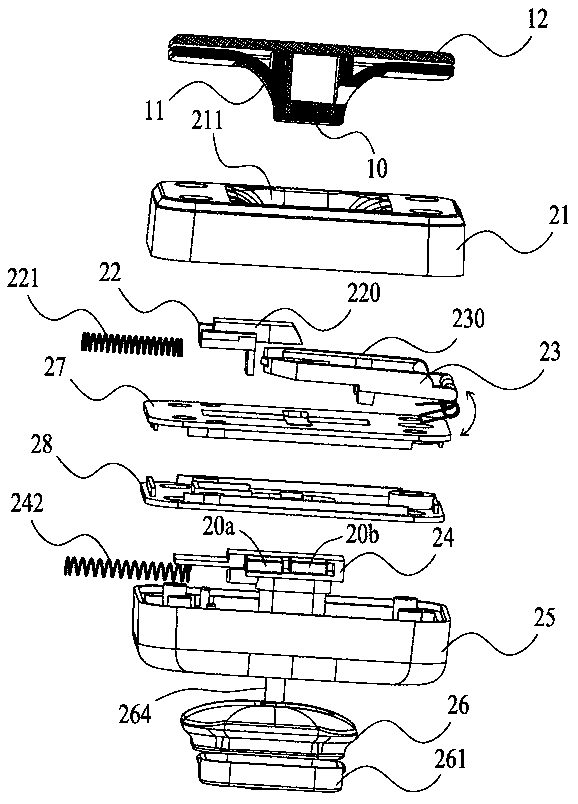
[0040] Compared with Embodiment 1, Embodiment 2 of the present invention provides a new type of magnetic buckle. In addition to utilizing the interaction between the first magnetic element 10 and the second magnetic element 20a and the third magnetic element 20b respectively, it also adds a mechanical structure At the same time, the fastening and separation of the first fastener 1 and the second fastener 2 are realized through the corresponding cooperation of the mechanical structure, which not only enhances the tightness and stability of the fastening, but also further improves the convenience of operation.

[0041] Please refer to image 3 As shown, the embodiment of the present invention provides a novel magnetic buckle, including a first buckle 1 and a second buckle 2 , and the first buckle 1 is detachably installed on the second buckle 2 .

[0042] Please combine Figure 4 As shown, the first fastener 1 includes a cover 12 , a first magnetic element 10 and a male buckle ...


PUM


Abstract

The invention provides a novel magnetic snap. The novel magnetic snap comprises a first snap piece and a second snap piece, wherein the first snap piece can be installed on the second snap in a separated mode, a first magnetic component is arranged in the first snap piece, a second magnetic component and a third magnetic component are arranged in the second snap piece in a line in an adjacent mode, and the second magnetic component and the third magnetic component can both be parallel to the first magnetic component and make linear motion. When the second magnetic component is opposite to the first magnetic component, the polarities of the opposite surfaces are opposite, and therefore the first snap piece and the second snap piece are buckled through mutual attraction of the first magnetic component and the second magnetic component. When the third magnetic component and the first magnetic component are opposite, the polarities of the opposite surfaces are identical, so that the first snap piece and the second snap piece are separated through mutual repulsive interaction of the third magnetic component and the first magnetic component. The novel magnetic snap is tight in buckling, convenient to operate and rapid in operation.

Description

technical field [0001] The invention relates to a locking device, in particular to a novel magnetic buckle. Background technique [0002] As a locking device, the magnetic clasp uses the magnetic attraction of a magnetic element (usually a magnet) to make two separate parts snap together. Common magnetic buckles usually include a male buckle and a female buckle, each with a magnetic element inside. When the male buckle and the female buckle are close, the polarity of the magnetic element in the male buckle is opposite to that in the female buckle. The principle of suction, the male buckle and the female buckle are fastened together. When separating, it is necessary to apply an external force that is opposite to the suction force of the magnetic element and greater than the suction force, and directly pull the male buckle out of the female buckle. Although this kind of magnetic buckle structure is simple, it is inconvenient to operate, especially if it is necessary to impro...

Claims


Application Information

Patent Timeline
Patent Type & Authority Applications(China)
IPC IPC(8): F16B17/00
CPCA44B99/00A44D2203/00F16B2200/83
Inventor 尔班·迈克尔
Owner 林汉雄
Why Eureka
Try Eureka