Method for controlling electronic equipment and electronic equipment

A technology of electronic equipment and control electronics, which is applied in control/regulation systems, non-electric variable control, vehicle position/route/altitude control and other directions. , the effect of simple operation

Active Publication Date: 2013-09-11
LENOVO (BEIJING) LTD
View PDF5 Cites 0 Cited by
  • Summary
  • Abstract
  • Description
  • Claims
  • Application Information

AI Technical Summary

Problems solved by technology

[0003] The present invention provides a method for controlling an electronic device and the electronic device, which are used to solve the problem of erroneous collisions caused by unknown objects in the navigation process in the prior art

Method used


Image

  • Method for controlling electronic equipment and electronic equipment
  • Method for controlling electronic equipment and electronic equipment
  • Method for controlling electronic equipment and electronic equipment

Examples


Embodiment Construction

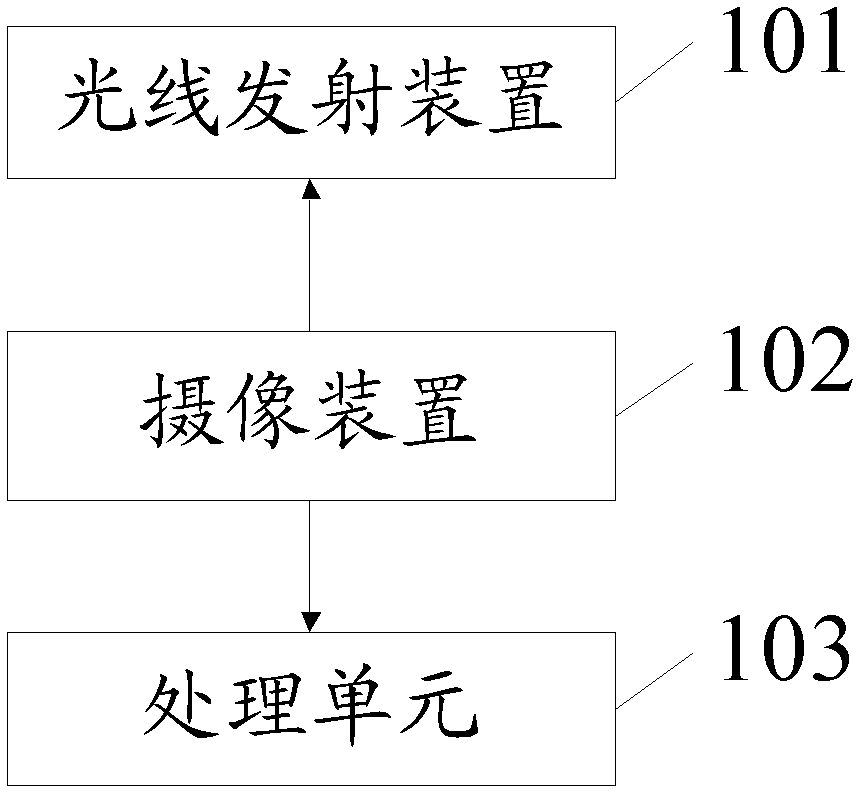
[0029] An embodiment of the present invention provides an electronic device, please refer to figure 1 , figure 1 is a functional block diagram of the electronic device in this embodiment.

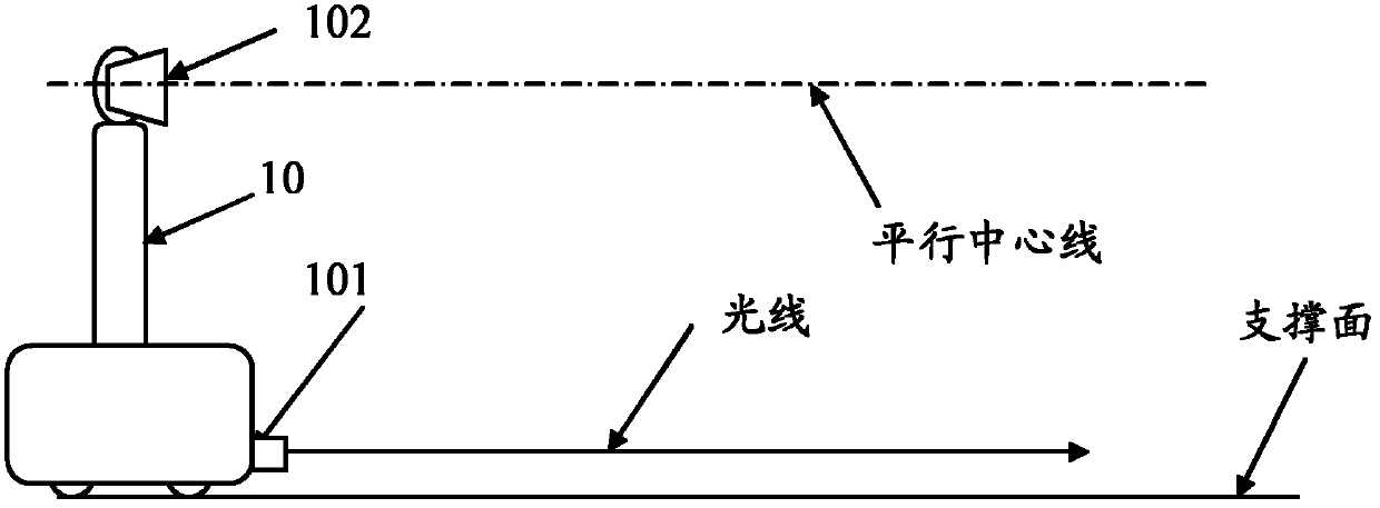
[0030] Please also refer to figure 1 and figure 2 , the electronic device 10 includes: a light emitting device 101 for projecting light, a camera device 102 , and a processing unit 103 .

[0031] In this embodiment, the light emitting device 101 and the camera device 102 are located on the same side of the electronic device 10, for example, both are located on the right side; The light projected by the device 101 is parallel; the height of the imaging device 102 relative to the support surface is greater than the height of the light emitting device 101 relative to the support surface, that is, as figure 2 As shown, the camera device 102 is located above the light emitting device 101 . Further, when the electronic device 10 is on the supporting surface, the light emitting device 101 c...


PUM


Abstract

The invention provides a method for controlling electronic equipment and the electronic equipment. The method is applied to the electronic equipment; the electronic equipment comprises a photographing device and a light emission device; and the method comprises the following steps of: determining whether an object exists in a view field range of the photographing device through the photographing device, wherein the object has a first state and a second state different from the first state; acquiring multiple light spots projected by the light emission device on the object through the photographing device in a motion process when the object exists in the view field range; and performing computational processing according to the multiple light spots, and determining the current state information of the object from the first state and the second state.

Description

technical field [0001] The invention relates to the technical field of intelligent control and computer application, in particular to a method for controlling electronic equipment and the electronic equipment. Background technique [0002] With the rapid development of smart mobile machines, users increasingly need smart mobile machines. However, in actual use, although the positions of some objects are drawn on the navigation map, such as objects with movable structures, such as door frames, the inventors found that the door is not marked as open on the navigation map. It is still closed, and even though it was marked at the beginning, because the door is a movable structure, it may be closed or opened at any time. When the door is closed, if the smart mobile machine still navigates according to the previous navigation map, it is very difficult May cause a mis-collision. Contents of the invention [0003] The present invention provides a method for controlling an electr...

Claims


Application Information

Patent Timeline
Patent Type & Authority Applications(China)
IPC IPC(8): G01C21/00G01V8/10
CPCG01C21/00G01V8/10G05D1/0246
Inventor 李众庆
Owner LENOVO (BEIJING) LTD
Why Eureka
Try Eureka